- SJ_Zhang
- Apr. 6, 2025
Abstract
Coincidence measurement of photon pairs over a large spatial mode is crucial for revealing non-classical phenomena and advancing quantum information technologies, which usually require an increased number of time-resolved single-photon detectors. Superconducting nanowire single-photon detectors stand out for their superior detection metrics and on-chip integration feasibility. However, their array frameworks usually only enable the localization of one photon. Here we propose a two-terminal two-photon coincidence counter using superconducting nanowire transmission lines with customized delay-time series. Using combinatorial time logic and amplitude multiplexing, our device successfully resolves all 152 potential single- and two-photon events in a 16-pixel configuration. Compared with traditional superconducting single-photon detector arrays, the device also exhibits a higher dynamic range in classical low-photon-flux sampling by efficiently suppressing multi-photon distortion. This innovative array architecture showcases self-coincidence counting, scalability and straightforward readout, making it promising for large-scale on-chip coincidence measurement in quantum information processing, as well as high-dynamic-range single-photon imaging and sensing in low-light environments.
Main
Multi-photon entanglement and interference are key in revealing strictly nonclassical phenomena. The generation of entangled photon pairs simply through laser-beam focusing onto a nonlinear optical crystal, along with single-photon manipulation and detection, has broad applications in fundamental quantum mechanics tests1,2 and innovative advancements including computation3,4,5, communication6 and sensing7,8,9. The progress in these areas benefits from the evolution of multi-channel multi-photon coincidence-measurement technologies that enable the characterization of spatial correlation and high-dimensional entanglement analysis. For instance, linear optical quantum computing relies on the coincidence detection of four paths and the ability to distinguish between zero, one and two photons3,4,5. Moreover, photonic quantum walk10,11,12,13 and Boson sampling14,15 hinge on the coincidence detection of single or entangled photons across numerous spatial modes. Moving forwards, the realization of large-scale photonic circuits for these quantum optical experiments demands an increasing number of time-resolved single-photon detectors16,17,18. Among the variety of single-photon detectors available, superconducting nanowire single-photon detectors (or SNSPDs) have gained prominence due to their outstanding performance metrics19,20 and potential for on-chip integration21. However, traditional SNSPD arrays that are designed for few-channel coincidence counting with the parallel readout of individual detectors encounter significant hurdles when expanded to a large number of channels22, particularly in terms of electrical readout.
Several multiplexing strategies have been explored to address the readout challenge, using methods such as row–column addressing23,24 and delay-time25, amplitude26 and frequency27 multiplexing. Although the implementation format is already very large28, these methods have focused primarily on determining the position of individual photons, and lack the capability to simultaneously measure multiple photons. This limitation arises because multi-photon coincidence detection in the array has an exponentially increased readout complexity with the number of photons and the indistinguishability of the multiplexed readout features. For example, amplitude multiplexing encodes the position and number of response pixels into the amplitude of the readout pulse, whose scalability is constrained by the signal-to-noise ratio of the pulse, thus the maximum number of pixels is only four so far29. Traditional delay lines face challenges in determining the positions of two photons, often resulting in a false one-photon position located at the midpoint (xi + xj)/2 between the two photon locations xi and xj along the nanowire. Only a few device structures have attempted to achieve the simultaneous resolution of multi-photon positions for a large spatial mode by connecting all pixels in series with delay lines30,31. Utilizing synchronous logic, single- and two-photon positions can be distinguished by jointly comparing the sum and difference of the pulse transmission time30. However, this method cannot cope with the absence of a reference time, especially in scenarios such as photon-pair detection pumped by continuous light sources10,11,12,13,32. On-chip inductors and resistors can also be connected in parallel for each pixel to facilitate rapid local current recovery after firing, which opens the transmission channel for the response pulse of multiple pixels31. It is necessary, however, for adjacent pixels to provide a nanosecond-level delay time and entails the integration of large-format circuits and heterogeneous materials. Moreover, none of the current schemes can distinguish the photon number detected on a single pixel.
Here we introduce a two-photon coincidence counter based on superconducting nanowire transmission lines, referred to as a superconducting nanowire two-photon coincidence counter (SNTPC). In contrast to previous device architecture that uses uniform delay-line lengths30,33, this coincidence counter topologically optimizes the delay-time series between adjacent pixels to distinguish the delay-time difference between pulse pairs from any one or two pixels. Utilizing combinatorial logic and amplitude multiplexing, we successfully showcase the ability to resolve all 152 possible single- and two-photon events in a 16-pixel device, including 16 single-photon cases, 120 cases of two photons hitting two different pixels (?162) and 16 cases of two photons on the same pixel. The SNTPC features an intrinsic self-coincidence counting capability, high scalability, streamlined fabrication processes, a straightforward two-terminal readout and the potential for waveguide integration, which are particularly suitable for two-photon coincidence detection in large-scale photonic integrated circuits.
Results
Topological optimization of the delay time
Delay-line-based single-photon imaging sensors determine the position of a single photon by analysing the delay-time difference of the pulse pair reaching the readout terminals25. In scenarios where two photons trigger the nanowire simultaneously, two pairs of positive and negative pulses are produced, but only the first-pulse edges closer to each terminal can be captured30, as illustrated in Fig. 1a. The current delay-line design, characterized by uniformity and symmetry in the delay time, presents a challenge in distinguishing between single-photon and two-photon events. This issue results in mistaking the midpoint along the nanowire where two photons hit as a single-photon position. The crucial idea for effectively resolving the locations of two photons is to break the symmetry of the delay line.
Fig. 1: Sixteen-pixel SNTPC.
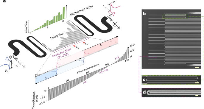
a, Schematic illustration of the device design and operation principle. The device is a two-terminal array that connects a chain of single-photon detector pixels (P1–P16) using a series of slow-wave delay lines of various lengths. Any case of a single photon or two photons hitting two different pixels can be distinguished by the delay-time difference (Δt = t1 − t2 (≡ tR − tL)) of the electrical pulses (V1 and V2) arriving at the two terminals (right and left). τn (n = 1–15), delay times of the delay lines between detector pixels. hν, photon. b, Scanning electron micrograph of the 16 detector pixels and partial delay lines. Scale bar, 10 μm. c, Enlarged view of a nanowire delay line. Scale bar, 2 μm. d, Close-up view of a detector pixel, which comprises a single meandering nanowire, specifically designed for potential waveguide integration. Scale bar, 0.5 μm. In all scanning electron micrographs, the darker regions represent niobium nitride (NbN), whereas the brighter regions denote the substrate where the NbN is etched away.
To address this problem, we can create a mathematical model to represent this delay process. Assuming that there are n pixels, then n − 1 segments of delay lines are required, with a sequence of delay times τk,k∈[1,n−1]. If two photons hit two positions Pi close to the left port and Pj close to the right port (1 ≤ i ≤ j ≤ n − 1, and i = j means only one triggered pixel encompassing single-photon and two-photon events), the propagating time from Pi to left port P1 is denoted as , and the propagating time from Pj to right port
 . Following the constraint criterion

where p and q are two virtual locations, we devised an iterative algorithm to generate the required delay-time sequence τk (see Methods). For a 16-pixel device, the delay-time sequence is (1, 2, 4, 5, 8, 10, 14, 21, 15, 16, 26, 25, 34, 22, 48) × τc, where τc is the minimum delay time associated with the jitter of the time difference. As shown in Fig. 1a, the calculated propagating time differences derived from the sequence τk,k∈[1,n−1] for arbitrary single- and two-photon events are distinct. Indeed, the inherent versatility of our design transcends the limitations of the 16-pixel configuration, affording direct scalability that can easily accommodate an increased pixel count. In Supplementary Section 4, we present a detailed analysis of a 64-pixel design, which demonstrates the robust scalability of our approach. It is pertinent to mention that the algorithm responsible for generating the delay-time series is an open mathematical challenge within the realm of optimization. There probably exists a more optimized delay-time series that could further reduce the overall delay time.
Device architecture and operation principle
Figure 1 illustrates the conceptual diagram and physical implementation of a 16-pixel SNTPC. The whole device is formed from a continuous superconducting nanowire in the coplanar waveguide structure. Sixteen detecting elements are connected by delay lines of various lengths, forming a linear array (Fig. 1b). Each detecting pixel is a single meandering nanowire with a width of 90 nm and a length of 40 μm (Fig. 1d). This specific design is intended for future integration with photonic waveguides34, where the transmission-line structure needs to be modified from a coplanar waveguide to a microstrip line to avoid the absorption of photons in the waveguide by the reference ground30 (Supplementary Section 5). Each meandered delay line has a width of 150 nm and a gap of 200 nm, resulting in a propagation velocity as slow as 4.4 μm ps−1 (1.48% of the speed of light in a vacuum). The shortest delay line is 240 μm (Fig. 1c), which corresponds to a minimum delay time τc of approximately 54 ps. The length and delay time of the other delay lines are multiplied according to the customized delay-time sequence τk,k∈[1,n−1]. Each end of the nanowire is connected to a Klopfenstein impedance taper to match the impedance between the delay lines (~2.7 kΩ) and the readout electronics (50 Ω)25. The long impedance tapers play a vital role in preserving the fast-rising edges and enabling sensitivity to photon-triggered hotspot resistance through the pulse amplitude26,35. The device was fabricated from a niobium nitride (NbN) film on a silicon substrate with a thermal dioxide layer. Fabrication details are provided in the Methods, and the basic characterization metrics are discussed in Supplementary Section 2.
The operational process of the SNTPC is illustrated in Fig. 1a. Regardless of whether the event involves a single photon or two photons, the left and right readout terminals consistently receive a pair of electrical pulses of opposite polarities. However, because the pulse duration (~100 ns) is significantly larger than the delay time (~1 ns), each terminal can only identify the pulse edge generated from its nearest pixel. To investigate the multi-photon response of the SNTPC, we used an attenuated 1,550 nm pulsed laser with a width of ~6 ps for experimental analysis. For each pair of detected pulses, we captured both the time difference Δt = t1 − t2 and the amplitude difference ΔV = V1 − V2. Figure 2a–c shows three kinds of typical cases: one photon on one pixel (Fig. 2a), two photons on one pixel (Fig. 2b) and two photons on two pixels (Fig. 2c), each showcasing distinct Δt and ΔV data. For resolving the single-pixel and two-pixel events, such as P9 and P9–P13, respectively, the time difference Δt function is used; for discriminating the photon number on the same pixel (for example, P9–P9), the amplitude difference ΔV is involved. As depicted in Fig. 2d, the distributions of two-dimensional (2D) points (Δt, ΔV/2) exhibit noticeable distinctions for the effective mean photon number per pulse ?~=0.002 and ?~=2. The value of ?~ encompasses the detector and coupling efficiencies, and is estimated by measuring the photon clicking probability ηclick = Rclick/frep and solving the equation 1−?−?~=?click, where Rclick is the photon clicking rate and frep is the repetition rate of the pulsed laser. When ?~=0.002, indicating the single-photon scenario, thus only 16 clusters of points exist (Fig. 2d, top). When ?~ is increased to ?~=2, an additional 120 clusters appeared in the otherwise vacant time-difference regions, accompanied by higher-amplitude points above the single-photon clusters (Fig. 2d, bottom). Therefore, by exploiting combinatorial logic and amplitude multiplexing, the SNTPC can achieve comprehensive two-photon coincidence counting, efficiently revealing all 152 possible single-photon and two-photon cases. This capability makes the SNTPC a versatile tool for diverse applications in the optical quantum field. A detailed analysis of the two features of time and amplitude are provided in the subsequent sections.
Fig. 2: Time–amplitude-multiplexed readout.
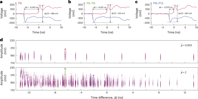
a–c, Pulse waveforms generated from the various photon-event cases: one photon on pixel P9 (a), two photons on pixel P9 (b) and two photons on pixels P9 and P13 (c). The pulse amplitudes are extracted from the first peak of the rising and falling edges. d, Measured 2D distributions of the time difference and amplitude show 16 distinguishable groups for ?~=0.002 (top) and 152 groups for ?~=2 (bottom). The dashed boxes mark the 2D points that correspond to the waveforms in a (P9), b (P9–P9) and c (P9–P13).
Complete two-photon coincidence counting
We first probe the features and performance of combinatorial logic in the SNTPC. Figure 3b shows the one-dimensional (1D) histograms of the time difference Δt at ?~=0.002 and ?~=2. For ?~=0.002 (Fig. 3b, top), the SNTPC shows only the single-photon response, and thus the time-difference distribution presents 16 distinct Gaussian peaks. The standard deviation of the peak counts was 7.7% of their mean, indicating a uniform efficiency of the pixels (Supplementary Fig. 4). For ?~=2, two-pixel events become prominent. As shown in Fig. 3b (bottom), the time-difference distribution shows 136 Gaussian peaks, implying that the combinatorial logic can resolve 136 cases, which includes single-pixel events (?161) and two-pixel events (?162). The observed higher counts at time difference Δt values approaching zero are attributed to these peaks containing more instances of three-or-more-pixel events. Compared with synchronous logic, which is dependent on the time of flight from a pulsed light source to the device, combinatorial logic operates independently without any reference time. Consequently, the SNTPC is also suitable for the coincidence counting of photon pairs pumped by a continuous-wave light source, which is a common practice in optical quantum science10,11,12,13,32.
Fig. 3: Combinatorial logic.
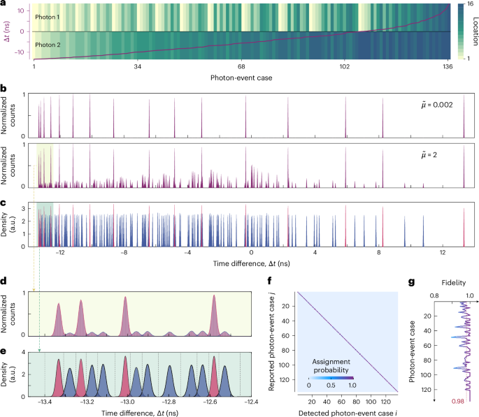
a, The correlation between photon-event cases and the time difference Δt. The time difference is arranged in ascending permutation, while the positions of the two photons are indicated using different colours, where the same colour within a photon-event case denotes either a single photon or two photons on one pixel. b, One-dimensional histogram of the time difference for ?~=0.002 (top) and ?~=2 (bottom). c, Normalized decomposed Gaussian distributions that fit the time-difference histograms in b, in which the single-pixel events are marked in red and the two-pixel events are shown in blue. d, Magnified section of the histograms in b. e, Magnified section of the fitting distributions in c, where the dashed lines denote the dividing thresholds. f, Confusion matrix illustrating the probabilities of assigning a detected photon-event case i to a reported case j, where the diagonal terms ??? represent the readout fidelity. g, Readout fidelity versus the photon-event case. The average fidelity is 0.98, indicating a high accuracy in assigning photon events. The colour scale in f also applies to g.
For insight into the resolving performances, we fitted the 136 peaks in the lower panel of Fig. 3b using Gaussian models to extract their positions and widths. Figure 3c shows 136 normalized Gaussian distributions Gi(t), whereas Fig. 3e shows an expansion of the first 13, where red shading denotes single-pixel events and blue shading marks two-pixel events. The time delays between adjacent Gaussian peaks of the single-pixel events are as follows: 0.054, 0.105, 0.208, 0.259, 0.414, 0.517, 0.724, 1.085, 0.775, 0.826, 1.340, 1.289, 1.753, 1.135 and 2.473 ns, in order. These values proportionally match the designed sequence τk,k∈[1,n−1] (1, 2, 4, 5, 8, 10, 14, 21, 15, 16, 26, 25, 34, 22 and 48). Therefore, we can establish the one-to-one mapping between photon-event cases and delay-time differences, as illustrated in Fig. 3a.
The time-difference distributions from single- and two-pixel events show marked discrepancies (Fig. 3e). For two-pixel events, the uncertainty in the time difference encompasses three sources of jitter: σΔ?2=2σdet2+σph2+2σele2, which results in a broader average full-width at half-maximum (FWHM) jitter of approximately 33 ps. Here, σdet denotes the intrinsic jitter of the detector (that is, the variable time delay with which an absorbed photon can trigger an electrical pulse), σph represents the jitter in the photon arrival time (that is, the variability in the time at which a photon may strike the detector within an optical pulse duration) and σele is the electrical jitter (that is, the temporal fluctuations in the trigger point on the rising edge of the pulse due to waveform instability and electrical noise). Conversely, in the case of single-pixel events, the uncertainty in the time difference stems solely from the electrical jitter of two pulses, expressed as σΔ?2=2σele2, and exhibits an FWHM of around 26 ps. By analysing these two time-difference distributions, we can further infer the intrinsic timing jitter of the device, which amounts to an FWHM of 14 ps (for details see Supplementary Section 3).
To assign a photon-event case j for an acquired delay-time difference time Δt, a series of dividing thresholds dk,1≤k≤137 need to be determined. This enables us to assign the photon event to a specific case j, if dj < Δt < dj+1. The dividing thresholds occur at the position of the intersection between two adjacent normalized Gaussian distributions Gi(t), as illustrated in Fig. 3e. To assess the accuracy of the photon-event assignments, we calculate the probability ??? of assigning a photon-event case j to an acquired time difference when actual case i occurs, which is described as

The confusion matrix of photon-event assignment in Fig. 3f provides insights into the readout fidelity, represented by ???. In the ideal situation, the confusion matrix will manifest as an identity matrix, with all diagonal terms equal to unity and all off-diagonal terms equal to zero. The readout fidelity values have an average of 0.98, and exceed 0.90 for all but two cases. Improved fidelities can be attained through the implementation of a longer delay time by slowing the transmission velocity30,31,36 or via lower electrical noise through using cryogenic amplifiers37.
The amplitude-multiplexed capability of the SNTPC can close the loopholes of two photons simultaneously hitting the same pixel, a scenario that was previously challenging to distinguish with existing coincidence-detection arrays30,31,38. Following the establishment of dividing thresholds dk,1≤k≤137, photon events within threshold-to-threshold regions of single pixels can be isolated to probe the photon number in each pixel, as depicted in Fig. 4a. The output-pulse amplitude Vout of an impedance-matched taper has demonstrated sensitivity to the photon-triggered hotspot resistance Rht (refs. 26,35,37,39), which includes the photon-number-related ?ht(?)∝? (refs. 40,41), at around the kilohm level. It can be calculated approximately via

where Zh = 2.7 kΩ is the characteristic impedance at the narrow end of the taper. Figure 4b shows the histograms of amplitude difference ΔV/2 across the 16 pixels. Level separations are obvious between the single- and two-photon amplitudes. The average separation between single- and two-photon peaks (20.7 mV) was about 4.3 standard deviations of their spread (4.8 mV), yielding a high distinguishing accuracy of over 95%. Although this readout resolution is not as optimal as previous results35, further improvement can be realized by optimizing the impedance and cut-off frequency of the taper35 or using cryogenic amplifiers37.
Fig. 4: Amplitude multiplexing.
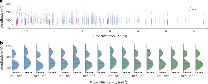
a, Partitioned 2D distributions of the time difference and amplitude for ?~=2, with the 2D points from single-pixel events highlighted in red. b, Histograms (bar) of the pulse amplitudes from 16 detector pixels, along with their Gaussian fitting decomposition shown as red dashed lines. The different colours from left to right of the histograms are used to label different detector pixels P1–P16.
High-dynamic-range photon-count mapping
Most of the superconducting single-photon imaging arrays can only resolve the position of one photon at a time23,24,25,26,28, thus they are often disturbed by multi-photon events in non-strict single-photon scenarios. Here we highlighted the advantages of the multi-photon resolution of the SNTPC by implementing the high-dynamic-range photon-count sampling of an optical fibre mode at various ?~ values. Our device elegantly circumvents the need for additional circuitry to manipulate the original signals or for complex processing methodologies to reconstruct the distribution, as each two-photon event is inherently distinguished by the time difference between the paired original pulses. Moreover, the complexity of the readout mechanism remains unaffected by the pixel number, with the requirement of just two readout channels to ascertain the spatial-state distribution of the photons. Figure 5a shows a schematic illustration and the statistical results in the single-photon regime (?~=0.002). The height of the red bars indicates the relative proportions of input photons detected by each detector pixel, the Gaussian fit of which (as shown by the black dashed curve) represents the mode of an SMF-28 optical fibre.
Fig. 5: Photon-count sampling of the optical mode.
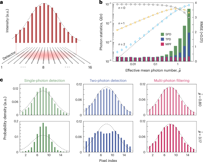
a, Schematic illustration of optical mapping. Red bars represent the relative photon counts detected at each detector pixel in the single-photon regime, whereas the black dashed curve denotes the Gaussian fit to portray the 1D optical intensity of the fibre mode. b, Photon-counting statistics (open symbols, left axis) and sampling errors (coloured bars, right axis) reconstructed from the time–amplitude points under different ?~ values. c, Typical reconstructed patterns using three methods (SPD, TPD and MPF) with ?~=0.80 (top) and ?~=3.17 (bottom). From b and c, it is clear that the MPF method consistently outperforms TPD, which in turn surpasses SPD.
First, we assessed the SNTPC’s capability of resolving single- and multi-photon events via measurement of the photon statistics for a pulsed coherent source. Figure 5b (left axis) shows the photon statistics Q(n) at different effective mean photons per pulse, with ?~ ranging from 0.002 to 3.17 in 2 dB increments. The measured counting results (open symbols) directly matched the Poisson distributions ?(?)=?−?~?~?/?! (dashed lines) without requiring a conditional probability30,42, because the cases of two photons hitting the same detector can also be discriminated by the amplitude-multiplexed readout.
For scenarios beyond single-photon interactions, we exploited three kinds of methods to reconstruct the optical mode. These methods include: (1) traditional single-photon detection (SPD), which is capable of identifying only single-photon locations, whereas it is prone to misinterpreting multi-photon events as single-photon occurrences at the middle position along the nanowire; (2) SNTPC-based two-photon detection (TPD), which enables the resolution of both single- and two-photon positions but is susceptible to disturbances from instances of three-or-more-photon events; and (3) SNTPC-based multi-photon filtering (MPF), which is designed to reject all multi-photon events and solely utilize single-photon locations. Figure 5c shows the sampling results for ?~=0.80 (top row) and ?~=3.17 (bottom row). In the case of ?~=0.80, the three methods generally recover the optical mode, with the MPF approach showing a superior performance in error reduction, outperforming TPD, which in turn surpasses SPD. When ?~=3.17, the MPF method continues to capture the optical mode accurately, whereas the TPD and SPD methods falter, with TPD yielding slightly better results than SPD.
Quantitative results in terms of the root mean squared error (RMSE) for various ?~ values from 0.002 to 3.17 with 2 dB increments are depicted in Fig. 5b (right axis). As ?~ is increased, the likelihood of multi-photon events rises, leading to worsening RMSE values for SPD and TPD. Owing to the two-photon imaging capability of the SNTPC, the RMSE of TPD is only half that of SPD. Given that the SNTPC can completely discriminate single- and multi-photon events, the MPF method remains unaffected by photon numbers, maintaining an excellent RMSE as small as that in single-photon scenarios. These findings validate the extended dynamic range beyond single-photon conditions offered by the proposed SNTPC. Although the work here demonstrates classical sampling at the multi-photon level, we expect that future large-format implementations will significantly enhance applications in quantum coincidence detection, such as integrated quantum photonics10,11,12,14,15,16,17,18 or quantum imaging7,8.
Conclusions
In summary, we have demonstrated an SNTPC with the topological optimization of delay-time series. Utilizing a hybrid time–amplitude multiplexing strategy, the combinatorial logic proves effective in discriminating between two photons striking different pixels, whereas the amplitude multiplexing enables the differentiation of two photons hitting the same pixel. This device obviates the requirement for supplementary circuitry to transform the original signals or processing methodology for reconstruction of the distribution, necessitating only two readout channels to ascertain the spatial-state distribution of the photon pairs. Moreover, the versatility of our approach extends beyond the 16-pixel configuration, enabling direct scalability to accommodate a higher number of pixels. With further optimization of the detection metrics, we predict that this innovative counting technology could boost a variety of cutting-edge applications in integrated quantum photonics16,17. From the classical measurement perspective, scaling up the array size through row–column integration24,28 paves the way towards advanced capabilities in multi-photon imaging and sensing applications.

Journal
Apr. 19, 2025
Journal
Apr. 19, 2025
Journal
Apr. 19, 2025
