• Laser & Optoelectronics Progress
  • Vol. 59, Issue 24, 2411002 (2022)
Qi Zhao1, Chen Tang1,*, Min Xu1, and Zhenkun Lei2
Author Affiliations
  • 1School of Electrical and Information Engineering, Tianjin University, Tianjin 300072, China
  • 2State Key Laboratory of Structural Analysis for Industrial Equipment, Dalian University of Technology, Dalian 116024, Liaoning, China
  • show less
    DOI: 10.3788/LOP202259.2411002 Cite this Article Set citation alerts
    Qi Zhao, Chen Tang, Min Xu, Zhenkun Lei. Background Removal of Fringe Projection Patterns Based on Modified Fuzzy c-Means Clustering Algorithm[J]. Laser & Optoelectronics Progress, 2022, 59(24): 2411002 Copy Citation Text show less
    Results comparison of first simulated fringe projection pattern. (a) Original fringe projection pattern; (b)-(d) Fig.1(a) corresponding theoretical background, fringe, and unwrapped phase; (b1)-(d1)corresponding results of FT on background, fringe, and unwrapped phase; (b2)-(d2) corresponding results of MOBEMD on background, fringe, and unwrapped phase; (b3)-(d3) corresponding results of TV-Hilbert-L2 on background, fringe, and unwrapped phase; (b4)-(d4) corresponding results of proposed method on background, fringe, and unwrapped phase; (e)-(e4) enlarged details corresponding to Fig.1(d)-(d4)
    Fig. 1. Results comparison of first simulated fringe projection pattern. (a) Original fringe projection pattern; (b)-(d) Fig.1(a) corresponding theoretical background, fringe, and unwrapped phase; (b1)-(d1)corresponding results of FT on background, fringe, and unwrapped phase; (b2)-(d2) corresponding results of MOBEMD on background, fringe, and unwrapped phase; (b3)-(d3) corresponding results of TV-Hilbert-L2 on background, fringe, and unwrapped phase; (b4)-(d4) corresponding results of proposed method on background, fringe, and unwrapped phase; (e)-(e4) enlarged details corresponding to Fig.1(d)-(d4)
    Results comparison of second simulated fringe projection pattern. (a) Original fringe projection pattern; (b)-(d) Fig.2(a) corresponding theoretical background, fringe, and unwrapped phase; (b1)-(d1) corresponding results of FT on background, fringe, and unwrapped phase; (b2)-(d2) corresponding results of MOBEMD on background, fringe, and unwrapped phase; (b3)-(d3) corresponding results of TV-Hilbert-L2 on background, fringe, and unwrapped phase; (b4)-(d4) corresponding results of proposed method on background, fringe, and unwrapped phase; (e)-(e4) enlarged details corresponding to Fig.2(d)-(d4)
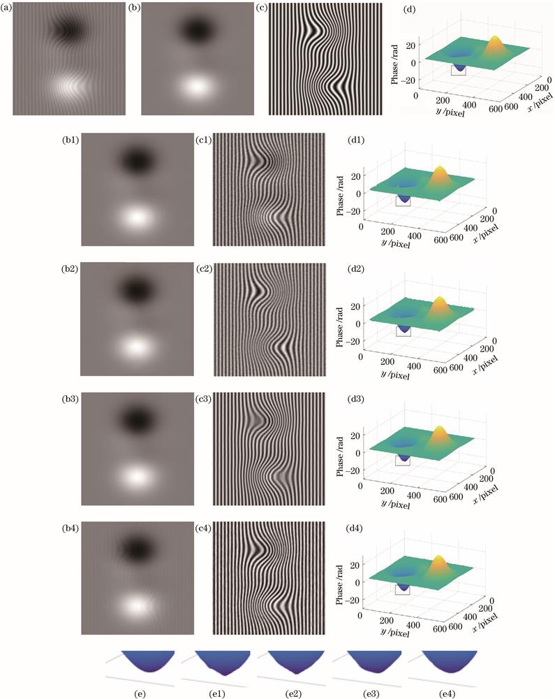
    Fig. 2. Results comparison of second simulated fringe projection pattern. (a) Original fringe projection pattern; (b)-(d) Fig.2(a) corresponding theoretical background, fringe, and unwrapped phase; (b1)-(d1) corresponding results of FT on background, fringe, and unwrapped phase; (b2)-(d2) corresponding results of MOBEMD on background, fringe, and unwrapped phase; (b3)-(d3) corresponding results of TV-Hilbert-L2 on background, fringe, and unwrapped phase; (b4)-(d4) corresponding results of proposed method on background, fringe, and unwrapped phase; (e)-(e4) enlarged details corresponding to Fig.2(d)-(d4)
    Results comparison of experimental fringe projection pattern. (a) Original fringe projection pattern; (b) corresponding theoretical unwrapped phase; (c1)-(e1) corresponding results of FT on background, fringe, and unwrapped phase; (c2)-(e2) corresponding results of MOBEMD on background, fringe, and unwrapped phase; (c3)-(e3) corresponding results of TV-Hilbert-L2 on background, fringe, and unwrapped phase; (c4)-(e4) corresponding results of proposed method on background, fringe, and unwrapped phase
    Fig. 3. Results comparison of experimental fringe projection pattern. (a) Original fringe projection pattern; (b) corresponding theoretical unwrapped phase; (c1)-(e1) corresponding results of FT on background, fringe, and unwrapped phase; (c2)-(e2) corresponding results of MOBEMD on background, fringe, and unwrapped phase; (c3)-(e3) corresponding results of TV-Hilbert-L2 on background, fringe, and unwrapped phase; (c4)-(e4) corresponding results of proposed method on background, fringe, and unwrapped phase
    Results comparison of noise performance test. (a) Original fringe projection pattern; (b) corresponding theoretical fringe; (c)-(g) fringe patterns obtained by proposed method after adding 0.2, 0.4, 0.8, 1, 1.2 Gaussian random noise respectively
    Fig. 4. Results comparison of noise performance test. (a) Original fringe projection pattern; (b) corresponding theoretical fringe; (c)-(g) fringe patterns obtained by proposed method after adding 0.2, 0.4, 0.8, 1, 1.2 Gaussian random noise respectively
    Fringe projection patternMethodSNRF /dBMSEp
    Fig. 1FT6.932.36×10-7
    MOBEMD9.511.39×10-7
    TV-Hilbert-L214.933.68×10-9
    Proposed method16.532.63×10-9
    Fig. 2FT10.528.63×10-7
    MOBEMD11.141.17×10-8
    TV-Hilbert-L216.493.10×10-9
    Proposed method16.822.66×10-9
    Table 1. Evaluation metrics on results for simulated fringe projection patterns
    Fringe projection patternMethodMSEp
    Fig. 3FT1.63×10-6
    MOBEMD4.25×10-7
    TV-Hilbert-L23.02×10-7
    Proposed method2.11×10-7
    Table 2. Evaluation metrics on results for experimental fringe projection pattern
    Qi Zhao, Chen Tang, Min Xu, Zhenkun Lei. Background Removal of Fringe Projection Patterns Based on Modified Fuzzy c-Means Clustering Algorithm[J]. Laser & Optoelectronics Progress, 2022, 59(24): 2411002
    Download Citation