 AI Video Guide
  AI Picture Guide
 AI One Sentence

Pengtao Luo, Fengyi Chen, Ruohui Wang, Xueguang Qiao, "Ultra-low loss Rayleigh scattering enhancement via light recycling in fiber cladding," Photonics Res. 12, 1813 (2024)
- Photonics Research
- Vol. 12, Issue 8, 1813 (2024)
Note: This section is automatically generated by AI . The website and platform operators shall not be liable for any commercial or legal consequences arising from your use of AI generated content on this website. Please be aware of this.
Abstract
1. INTRODUCTION
Distributed optical fiber sensors (DOFS) have demonstrated significant values in the structural health inspection, biomedicine, and aerospace industries by providing continuous measurements of strain and temperature monitoring at more than a few thousand locations at low cost and small size along the length of an optical fiber [1,2]. Commercially available communication fibers have become the mainstream fiber used in DOFS because of the advantages of low cost and standardization, but the backscattering light of standard fibers is designed to be as low as possible, which seems to be contrary to the needs of Rayleigh scattering based distributed sensing. Therefore, recent research has focused on new fibers with higher backscattering to improve the resolution and accuracy of the sensing system [3,4].
Techniques to enhance Rayleigh backscattering can be divided into two categories: special fibers with composition changes and modifications to standard fibers. Doping (germanium) in fiber core is a straightforward way to correlate with Rayleigh scattering, and the doped components increase the inhomogeneity of the core material, which in turn enhances Rayleigh scattering [5]. Doping nanoparticle engineering (
Femtosecond lasers can preserve the fiber coating to process the fiber and do not require photosensitivity enhancement. In particular, the permanent modifications formed by femtosecond lasers have higher temperature stability (
Sign up for Photonics Research TOC. Get the latest issue of Photonics Research delivered right to you!Sign up now
Here we show a cladding-type Rayleigh scattering enhancement (cl-RSE) structure with ultra-low loss in the single-mode fiber (SMF). The structure is composed of refractive-index modulation points inscribed in the fiber cladding close to the core using the femtosecond laser point-by-point inscription method. Actually, the mode field diameter of the SMF is slightly larger than the geometric diameter of the core, which results in the vast majority of the transmitted light being concentrated in the core, with only a small portion of the energy in the cladding in the form of an evanescent field. The cl-RSE structure simply disrupts the wave-vector propagation direction of the evanescent field, and part of the light is recycled in the form of backward Rayleigh scattering. This process does not involve the transmitted light in the core, which results in extremely low IL values. The effects of the offset from the core edge, the pulse energy, and the interval between scatterers on the Rayleigh backscattering intensity are investigated. After optimizing the inscription parameters, the loss characteristics and the behavior at high temperatures of the cl-RSE structure are tested, and the cl-RSE structure has a 10 times lower loss than the core-RSE structure. Meanwhile, it exhibits superior stability at high temperatures. The cl-RSE structure with ultra-low loss may have application potential for improving the performance aspects of distributed sensors.
2. DEVICE FABRICATION AND CHARACTERIZATION
The SMF used in the experiments was a standard commercial silica-core fiber (Corning, SMF-28 Ultra, 8.2/125 μm) without any pre-processing, and the fiber was fixed on a high-precision three-dimensional displacement stage (Newport, XMS100). A femtosecond laser with a wavelength of 800 nm and a pulse duration of 50 fs was used, and the laser repetition frequency was fixed at 200 Hz. The Gaussian femtosecond laser beam was focused by a microscope objective (
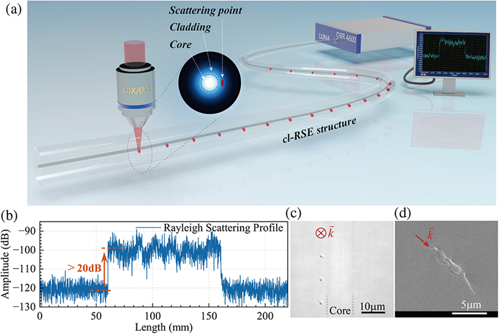
Figure 1.(a) Schematic diagram of the cl-RSE structure preparation (inset shows the position of the cl-RSE structure in the electric mode field of the fiber). (b) Rayleigh backscattering profile of a 100 mm long cl-RSE structure. (c) Optical micrograph of the side of the cl-RSE structure. (d) SEM image of the fiber cross section with a modulation point.
Images of the sides of the cl-RSE structure were recorded by optical microscopy, as shown in Fig. 1(c). The cl-RSE structure was set with an interval of 10 μm between the scatterers and 2 μm offset from the core edge, and no additional modulation points appeared in the fiber core. Then, the cl-RSE fiber section was cleaved and the morphology of its cross section was observed by SEM. Figure 1(d) shows the SEM image of the eccentric refractive-index modulation point, and it can be observed that the modulation point is composed of sub-micrometer period nano gratings and that the cladding nano gratings are similar to the structure of femtosecond laser-induced self-organized nano gratings [15,20].
In order to demonstrate the scattering operation of the cl-RSE structure in the fiber, we simulated the electric field mode distribution on the side of the fiber using the finite element simulation method, as shown in Figs. 2(a) and 2(b). The parameters of a standard SMF-28 Ultra fiber (
![]()
Figure 2.(a) 2D model setup of the cladding refractive-index modulation point in SMF. (b) Periodic refractive-index distribution in the cladding. (c) Electric field mode distribution with 100 cladding scatterers in the SMF; fiber length set to 3 mm. (d) Electric field mode intensity distribution of
The effect of different cl-RSE structures on the enhancement of backscattered signals is shown in Fig. 3, where we focused on three distinct parameters: the offset from the core edge, the pulse energy, and the interval between the scatterers. Micrographs of representative samples at different parameters are shown in Fig. 3(a). The offsets of the modulation points were set to vary from 1 to 5 μm in 1-μm steps. At the same time, the Rayleigh scattering profiles in the fiber were recorded with the OBR, and the enhancement of the backscattered signal strengths in the inscribed portion was accounted for in Fig. 3(b). No significant RSE was observed in the OBR beyond 5 μm. In addition, the RSE effect was more pronounced the closer the cl-RSE structure was to the core, which was due to the Gaussian distribution of the optical field in the SMF, where the intensity in the cladding had a sharp attenuation along the radius to zero compared to the vast majority of the energy present in the core, and this phenomenon was also reflected in the enhancement of the Rayleigh scattering at the scatterer of the cladding.
![]()
Figure 3.Effect of different cl-RSE structures on the enhancement of backscattered signals. (a) Micrographs of representative samples at different parameters. (b) Statistics of Rayleigh scattering enhancement at different offsets and pulse energies. (c) Statistics of Rayleigh scattering enhancement at different intervals. (d) The backscattering profile of 11 scatterers spaced at 2000 μm intervals allows the backscattering enhancement of each point to be clearly distinguished.
Six cl-RSE structures with an interval of 10 μm and an offset of 2 μm were prepared by increasing the laser single pulse energy from 248 to 310 nJ, and the corresponding RSEs were recorded in Fig. 3(b). As the energy increased, the color of the modulation points in the micrographs was deepened and there was a slight increase in the size of the modulation points, as shown in Fig. 3(a), where the enhancement of the backward signal strength increased with the increase in pulse energy. However, when the energy continues to increase, the modulation region in the micrograph shows a significant outward expansion, probably because the laser energy reaches the threshold of the void-type modulation [26]. The expansion of the refractive-index modulation region into the fiber core brings additional loss. Therefore, the laser energy was kept at a moderate 285 nJ in the subsequent experiments to obtain a more stable scattering enhancement.
We prepared cl-RSE structures with different intervals, and the repetition frequency of the pulsed laser was 200 Hz to change the moving speed of the fiber (
The modulation points with an interval of 2000 μm were prepared in a length of 20 mm, and Fig. 3(d) shows the 11 measured modulation points, which can clearly distinguish the position of each modulation point and facilitate the analysis of the action of individual modulation points. The results show that even only one refractive-index modulation point can provide more than 20 dB enhancement of the backscattered signal, while there is a 9 dB difference in the enhancement due to the dependence of the cl-RSE on the offset and laser energy instability. To balance this discrepancy, the interval of the cl-RSE fiber used for subsequent characterization was chosen to be 10 μm.
3. RESULTS AND DISCUSSION
A. Insertion Loss of cl-RSE Structures
![]()
Figure 4.(a) IL for different numbers of scatterers; inset shows the trend of average IL. (b) Transmission spectra of the cl-RSE structure in the 1000 nm range, which did not exhibit wavelength-dependent absorption.
The wavelength dependence of the cl-RSE structure was characterized. The transmission spectra were measured using a supercontinuum light source (NKT, Superk Compact) and an optical spectrum analyzer (Yokogawa, AQ6370D). Figure 4(b) shows the transmission spectra of a 100 mm long fiber sample in the range of 700–1700 nm and no significant loss of wavelength in the 1000 nm range. Transparent transmission in the NIR band promotes the application of cl-RSE fiber in the integration of communication and sensing.
B. High Performance Temperature Sensing Using cl-RSE Fiber
Femtosecond laser-prepared FBGs [14], Rayleigh scattering centers [15], and micro-cavity arrays [16] have shown excellent reliability in measurements at high temperatures. In the test, the spatial resolution of the OBR was set to 0.1 mm, and the wavelength scanning range was 1530.000–1571.713 nm. A 100 mm long cl-RSE fiber was used to test high-temperature characteristics. The temperature was set to cycle from room temperature to 800°C [Fig. 5(a)], with the temperature increasing by 50°C every 10 min and remaining stable for 20 min. The frequency shift in the three temperature cycles is shown in Fig. 5(b), where the temperature response of the cl-RSE fiber is about 1.7–1.8
![]()
Figure 5.High-temperature testing of cl-RSE fiber. (a) Schematic of cl-RSE fiber placed in a tube furnace. (b) Temperature response of 100 mm long cl-RSE fiber at 0°C–800°C for three temperature cycles. (c) Long-term stability of 100 mm long cl-RSE fiber at different temperatures: (c1) 800°C, (c2) 900°C, and (c3) 1000°C. Temperature measurement fluctuations of cl-RSE fiber (d) before and (e) after annealing at 800°C.
The long-term stability of cl-RSE fiber is shown in Figs. 5(c1)–5(c3). We prepared three 100 mm long cl-RSE fibers with the same parameters and kept them at 800°C, 900°C, and 1000°C for 10 h. Finally, they were naturally cooling down to room temperature, and the Rayleigh scattering profiles in the fibers were monitored every half an hour during the high-temperature holding. The results showed that the Rayleigh scattering profile at 800°C did not change compared to that at room temperature. Meanwhile, some additional scatterers appeared in the Rayleigh scattering profile when the sample fiber was heated at 900°C for 6 h. At 1000°C, more scatterers appeared after only 2.5 h. The appearance of these scatterers may be due to additional defects above 800°C when the silica starts to soften. However, the Rayleigh scattering intensity enhancement caused by the cl-RSE structure is still clearly visible, indicating that the cladding scatterers can survive at 1000°C [29,30]. These results suggest that the fiber used in the experiments softens above 800°C and that the fragile fiber itself is a major constraint on the sensing performance after softening.
An exciting point is that the cl-RSE fiber demonstrated higher stability than the unmodulated fiber. Temperature stability measurements were made by first measuring the Rayleigh scattering characteristics once at room temperature, and this data was stored as a shift reference. Keeping the fiber position and temperature, etc., constant, measurement was taken once after 10 min, and the amount of temperature change was recorded. The results in Fig. 5(d) show that the temperature fluctuation of a 100-mm portion of the cl-RSE fiber is 0.0262°C, which is a factor of 2.3 lower than that of the unmodulated fiber. After annealing at 800°C as described above, we tested the temperature fluctuation in the same way and found that the temperature fluctuation of the cl-RSE fiber portion is only 0.00273°C, which is nearly 10 times lower compared to that before annealing and 9.1 times lower than that of the unmodulated fiber portion [Fig. 5(e)]. The annealing process eliminates defects such as stress residues at the modulation point. This result shows that the cl-RSE structure enhances the backscattered intensity by about 20 dB, which improves the temperature measurement accuracy by about 10 times. Using fibers with cl-RSE structure is expected to realize ultra-high accuracy temperature measurement at high temperatures.
4. CONCLUSION
In summary, we proposed and demonstrated an ultra-low loss Rayleigh scattering enhancement structure in SMF by recycling light in cladding. The cl-RSE structure is inscribed into the cladding of SMF by the femtosecond laser point-by-point direct-writing technology. The simulation results show that the cl-RSE structure is able to enhance scattering in the fibers efficiently without affecting the forward transmitted light in the core. In addition, the scattering enhancement capability of the cl-RSE structure is shown to be flexibly controlled by offset distance, interval, and pulse energy, providing at least 20 dB of scattering signal enhancement per scatterer under suitable parameters. We tested the corresponding IL and demonstrated an IL as low as 0.00001 dB per scatterer, which is 10 times lower than that of the scattering enhancement structure in the fiber core. Finally, the cl-RSE fiber was characterized at high temperatures with a temperature response of about 1.7–1.8
References
[27] P. Luo, F. Chen, R. Wang. Femtosecond laser inscription of eccentric waveguide in optical fiber for rayleigh scattering enhancement. CLEO: Fundamental Science, JW2A-26(2023).


Set citation alerts for the article
Please enter your email address

© Copyright 2018-2021 | Chinese Laser Press. All Rights Reserved 沪ICP备15018463号-20