• Laser & Optoelectronics Progress
  • Vol. 59, Issue 14, 1415013 (2022)
Anhu Li*, Wenjie Luo, Xingsheng Liu, and Zhaojun Deng
Author Affiliations
  • School of Mechanical Engineering, Tongji University, Shanghai 201804, China
  • show less
    DOI: 10.3788/LOP202259.1415013 Cite this Article Set citation alerts
    Anhu Li, Wenjie Luo, Xingsheng Liu, Zhaojun Deng. 3D Reconstruction of Array Virtual Camera[J]. Laser & Optoelectronics Progress, 2022, 59(14): 1415013 Copy Citation Text show less
    Experimental system model
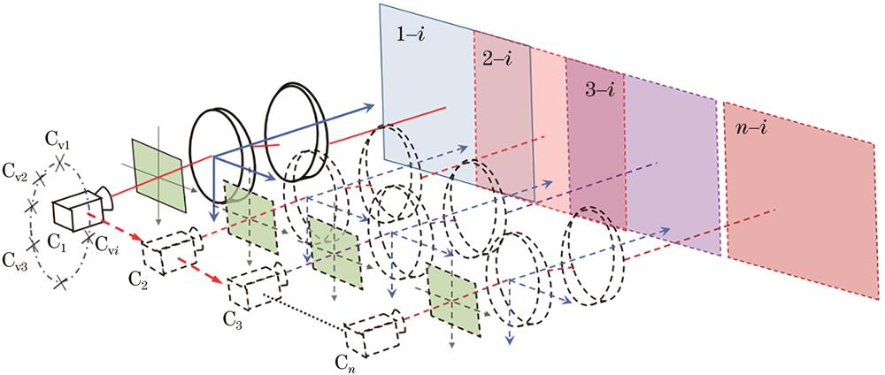
    Fig. 1. Experimental system model
    Rotating Risley prism model
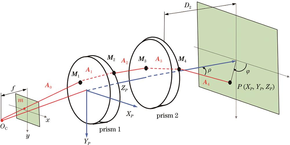
    Fig. 2. Rotating Risley prism model
    Spatial point imaging diagram of adjacent array virtual cameras
    Fig. 3. Spatial point imaging diagram of adjacent array virtual cameras
    Imaging diagram of virtual camera
    Fig. 4. Imaging diagram of virtual camera
    Simulation of overlapping view of array virtual camera
    Fig. 5. Simulation of overlapping view of array virtual camera
    Position diagram of virtual camera coordinate system
    Fig. 6. Position diagram of virtual camera coordinate system
    Captured binocular images, the first row corresponds to the angle combination (30°, 150°), (15°, 165°), and the second row corresponds to the angle combination (0°, 180°), (-15°,-165°)
    Fig. 7. Captured binocular images, the first row corresponds to the angle combination (30°, 150°), (15°, 165°), and the second row corresponds to the angle combination (0°, 180°), (-15°,-165°)
    Original point cloud
    Fig. 8. Original point cloud
    Overlapping point clouds. (a) The first pair; (b) the second pair; (c) the third pair
    Fig. 9. Overlapping point clouds. (a) The first pair; (b) the second pair; (c) the third pair
    The first pair of point cloud registration. (a) ICP results with pre-coarse registration; (b) ICP results without coarse registration
    Fig. 10. The first pair of point cloud registration. (a) ICP results with pre-coarse registration; (b) ICP results without coarse registration
    The second pair of point cloud registration. (a) ICP results with pre-coarse registration; (b) ICP results without coarse registration
    Fig. 11. The second pair of point cloud registration. (a) ICP results with pre-coarse registration; (b) ICP results without coarse registration
    The third pair of point cloud registration. (a) ICP results with pre-coarse registration; (b) ICP results without coarse registration
    Fig. 12. The third pair of point cloud registration. (a) ICP results with pre-coarse registration; (b) ICP results without coarse registration
    The final splicing result. (a) Point cloud diagram; (b) point cloud coloring diagram
    Fig. 13. The final splicing result. (a) Point cloud diagram; (b) point cloud coloring diagram
    Camera internal parameterRotation matrix RTranslation matrix T
    8119.480794.2908119.62643.320010.9999-0.00820.00780.00810.99990.0024-0.0079-0.00240.9999-100.277.469.41
    Table 1. Internal and external parameters of camera
    Experiment groupTime cost of ICP /sTime cost of proposed method /sImprovement /%
    Total0.810.6223
    The first group0.350.2529
    The second group0.210.1814
    The third group0.250.1924
    Table 2. Comparison of point cloud registration time