• Advanced Imaging
  • Vol. 2, Issue 1, 011002 (2025)
Zhengyang Wang1,2,†, Daixuan Wu3, Yuecheng Shen1,2,4,*, Jiawei Luo1,2..., Jiajun Liang1,2, Jiaming Liang1,2, Zhiling Zhang2, Dalong Qi2, Yunhua Yao2, Lianzhong Deng2, Zhenrong Sun2 and Shian Zhang2,4,5,*|Show fewer author(s)
Author Affiliations
  • 1School of Electronics and Information Technology, Sun Yat-sen University, Guangzhou, China
  • 2State Key Laboratory of Precision Spectroscopy, School of Physics and Electronic Science, East China Normal University, Shanghai, China
  • 3Guangdong Provincial Key Laboratory of Nanophotonic Functional Materials and Devices, South China Normal University, Guangzhou, China
  • 4Collaborative Innovation Center of Extreme Optics, Shanxi University, Taiyuan, China
  • 5Joint Research Center of Light Manipulation Science and Photonic Integrated Chip of East China Normal University and Shandong Normal University, East China Normal University, Shanghai, China
  • show less
    DOI: 10.3788/AI.2025.10024 Cite this Article Set citation alerts
    Zhengyang Wang, Daixuan Wu, Yuecheng Shen, Jiawei Luo, Jiajun Liang, Jiaming Liang, Zhiling Zhang, Dalong Qi, Yunhua Yao, Lianzhong Deng, Zhenrong Sun, Shian Zhang, "Coded self-referencing wavefront shaping for fast dynamic scattering control," Adv. Imaging 2, 011002 (2025) Copy Citation Text show less

    Abstract

    Wavefront shaping enables the transformation of disordered speckles into ordered optical foci through active modulation, offering a promising approach for optical imaging and information delivery. However, practical implementation faces significant challenges, particularly due to the dynamic variation of speckles over time, which necessitates the development of fast wavefront shaping systems. This study presents a coded self-referencing wavefront shaping system capable of fast wavefront measurement and control. By encoding both signal and reference lights within a single beam to probe complex media, this method addresses key limitations of previous approaches, such as interference noise in interferometric holography, loss of controllable elements in coaxial interferometry, and the computational burden of non-holographic phase retrieval. Experimentally, we demonstrated optical focusing through complex media, including unfixed multimode fibers and stacked ground glass diffusers. The system achieved runtime of 21.90 and 76.26 ms for 256 and 1024 controllable elements with full-field modulation, respectively, with corresponding average mode time of 85.54 and 74.47 µs—pushing the system to its hardware limits. The system’s robustness against dynamic scattering was further demonstrated by focusing light through moving diffusers with the correlation time as short as 21 ms. These results emphasize the potential of this system for real-time applications in optical imaging, communication, and sensing, particularly in complex and dynamic scattering environments.

    1. Introduction

    Optical speckles arise from the random interference of light after its path is disrupted by scattering media. Similarly, in multimode fibers (MMFs), mode crosstalk—where theoretically orthogonal spatial modes interfere due to imperfections, bending, and environmental factors—produces speckles at the output. In both cases, these random and disordered speckles complicate the retrieval of the original information, posing a long-standing challenge in optical information transmission[1,2]. Recent breakthroughs in wavefront shaping offer a powerful solution by transforming what was once a chaotic obstacle into a controllable process. By treating the scattering medium as a deterministic transmission matrix, wavefront shaping enables precise manipulation of scattered light, restoring a one-to-one mapping between input and output modes[36]. Phase conjugation, which reverses the scattering process by retracing the light’s original path, has demonstrated remarkable accuracy in refocusing scattered light[711]. This advancement is particularly valuable in biomedical imaging, where tissue scattering limits imaging depth. Moreover, wavefront shaping mitigates mode crosstalk in MMFs[1219], improving signal integrity and transmission efficiency in communication, sensing, and endoscopy applications[2023].

    However, real-world applications introduce additional complexities, as dynamic environments—such as moving scatterers in tissue or changing conditions in MMFs—cause the transmission matrix to evolve rapidly and unpredictably, complicating stable control[2326]. This challenge is particularly pronounced in freely positioned MMFs and live biological tissues, where internal fluctuations and external disturbances affect the deterministic nature of the scattering process. In such cases, adaptive, real-time wavefront shaping systems are essential[27]. System efficiency is governed by the average mode time—the time required to measure and control each independent mode or element[26,28,29]. It is defined as the ratio of the total system runtime to the product of the number of independent modes and the modulation efficiency. By dividing the optical speckles’ correlation time (the time scale of the dynamic process) by the average mode time, one can determine the number of modes that can be effectively controlled in a given dynamic scattering environment. The shorter the average mode time, the more modes that can be controlled before the speckle patterns change. As a result, fast wavefront shaping systems are essential for maintaining optimal performance in dynamic environments.

    Researchers have been actively developing fast wavefront shaping systems to reduce average mode time. As most time is spent on wavefront measurement, these techniques can be broadly categorized into those using external reference light and those that do not. Systems employing interferometric holography are generally faster but more susceptible to environmental disturbances. For example, utilizing the time-reversal symmetry of wave equations can retrieve a single row of the transmission matrix in tens of nanoseconds[2932], and acousto-optic frequency encoding has achieved average mode time of a few microseconds[33,34]. However, these systems rely on external reference light and require complex alignment, making them vulnerable to environmental factors. In contrast, referenceless wavefront shaping systems offer greater robustness. Feedback-based systems, which use optimization algorithms, eliminate the need for reference light but are less efficient due to repeated communication between wavefront measurement and control, resulting in average mode time in the millisecond range[3538]. Neural networks can also be employed to determine the transmission matrix, but the time-intensive processes of generating training datasets and training the networks limit their real-time performance[3945]. A simpler alternative is direct transmission matrix measurement through coded wavefronts using coaxial interferometry[4,4648] or non-interferometric phase retrieval[4954]. With digital micromirror devices (DMDs) operating at tens of kHz, state-of-the-art systems have achieved average mode time of 185 µs using coaxial interferometry[55] and 95 µs with non-interferometric phase retrieval[26]. However, coaxial interferometry sacrifices a fraction of controllable elements to serve as static reference lights, while non-interferometric phase retrieval demands significant computational resources, limiting scalability for large transmission matrices[56,57].

    To address the aforementioned challenges, we propose a coded self-referencing method that overcomes the limitations of both coaxial interferometry and non-interferometric phase retrieval, enabling fast measurement and control of dynamic scattering. This method eliminates the need for static references in coaxial interferometry, thereby preserving the number of controllable elements and avoiding the computational complexity associated with non-interferometric phase retrieval. By employing superpixel encoding with a DMD[58] (as detailed in Appendix A), we directly synthesize interference patterns of orthogonal bases and a planar reference to probe the complex medium, enabling efficient three-step phase-shifting to extract the complex coefficients of orthogonal basis modes (explained in Appendix B). This approach allows for rapid, large-scale transmission matrix measurement and full-field wavefront control with minimal computational overhead, significantly enhancing wavefront shaping performance. Specifically, we achieved millisecond-level system runtime of 21.90 and 76.26 ms for 256 and 1024 controllable elements with full-field modulation, corresponding to average mode time of 85.54 and 74.47 µs, respectively, reaching the system’s hardware limit. As a proof of concept, we demonstrated optical focusing through unfixed MMFs and moving diffusers, showcasing the system’s ability to effectively overcome dynamic scattering and mode crosstalk.

    2. Results

    2.1. Operational Principle of the Coded Self-Referencing Method

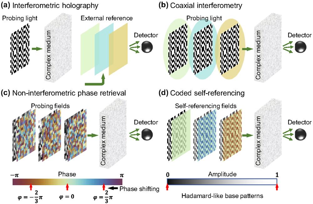
    Figure 1 illustrates the operational principle for measuring the transmission matrix of a complex medium. A series of orthogonal bases, such as Hadamard bases[4,47,59,60], are generated to interact with the medium, producing speckle patterns [Fig. 1(a)]. The transmission matrix is then directly calculated by summing the Hadamard bases (reshaped from two-dimensional matrices to one-dimensional rows) with the associated optical fields as complex coefficients. In setups where reference light is introduced after the complex medium, as in a typical interferometric holographic configuration [Fig. 1(a)][61], the true transmission matrix is determined using a direct three-step phase-shifting method. Alternatively, when the reference light is introduced before the medium, the system operates as a coaxial interferometric setup [Fig. 1(b)][4,46]. If no reference light is used, the system functions as a non-interferometric phase retrieval setup [Fig. 1(c)][26,49,50,56]. It should be noted that in the latter two configurations, each row of the transmission matrix contains unknown complex coefficients.

    Schematic illustration of the operational principles for various transmission matrix measurement methods. (a) Interferometric holographic configuration: Reference light is introduced after the complex medium, enabling transmission matrix measurement using a three-step phase-shifting method. (b) Coaxial interferometric setup: Reference light is introduced before the complex medium, facilitating transmission matrix measurement. (c) Non-interferometric phase retrieval: No reference light is used, relying on phase retrieval techniques to determine the transmission matrix. (d) Proposed coded self-referencing method: Probing light (Hadamard bases) and reference light (three-step phase-shifted) are synthesized, enabling transmission matrix measurement while preserving all controllable elements.

    Figure 1.Schematic illustration of the operational principles for various transmission matrix measurement methods. (a) Interferometric holographic configuration: Reference light is introduced after the complex medium, enabling transmission matrix measurement using a three-step phase-shifting method. (b) Coaxial interferometric setup: Reference light is introduced before the complex medium, facilitating transmission matrix measurement. (c) Non-interferometric phase retrieval: No reference light is used, relying on phase retrieval techniques to determine the transmission matrix. (d) Proposed coded self-referencing method: Probing light (Hadamard bases) and reference light (three-step phase-shifted) are synthesized, enabling transmission matrix measurement while preserving all controllable elements.

    Figure 1(d) illustrates the proposed coded self-referencing method, which synthesizes the combined optical field of probing light (Hadamard bases) and reference light (three-step phase-shifted) to interact with the complex medium (as detailed in Appendix C). A similar encoding scheme has recently been applied for holographic imaging in clear media, primarily under static conditions[57]. This method retains the stability advantages of a referenceless setup while employing field encoding to reduce the computational complexity involved in reconstructing the transmission matrix. As with coaxial interferometry and non-interferometric phase retrieval, each row of the resulting transmission matrix contains unknown complex coefficients. However, these unknown coefficients do not adversely affect system performance when focusing light at specific spatial positions. In contrast to feedback-based methods[59,6264], our coded self-referencing approach allows for efficient transmission matrix reconstruction without the need for persistent feedback. Additionally, this method eliminates the need for dedicated reference fields, optimizing the use of available modes and reducing computational complexity, which is crucial for applications involving large and dynamically changing transmission matrices.

    2.2. Experimental Setup

    We constructed an experimental setup to demonstrate the coded self-referencing method and validate its operational principle. As shown in Fig. 2, a continuous-wave laser (MSL-FN-532-100mw, CNI) was used as the light source, with the beam expanded to a 1-inch diameter to fully illuminate the DMD (V-7001, Vialux). A superpixel encoding scheme was employed, grouping every 4pixel×4 pixel into one superpixel[58]. The light diffracted from the DMD was spatially filtered to pass only the 1st diffraction order, enabling the selective generation of beams with varying amplitude and phase at the imaging plane of a 4f system. To achieve fast DMD refresh rates, a central active zone of 256pixel×1024 pixel was selected, providing a refresh time of 23 µs, corresponding to a refresh rate of approximately 43.48 kHz. The selected active zone facilitates higher optical energy coupling through the MMF, supported by a higher refresh rate and compatible with complex-field modulation. Opting for a 1:1 aspect ratio, however, reduces the refresh rate to 22.7 kHz. The modulated light was then coupled into a 1-m-long MMF (FC/PC-FC/PC-50/125-900 µm, Shenzhen Optics-Forest Inc.). Additionally, stacked ground glass diffusers (DG10-1500, Thorlabs) were used as the scattering media. A polarizer (LPVISA100-MP2, Thorlabs) was placed after the complex media to detect light with a specific polarization state. The output intensity distribution was captured by an avalanche photodiode (APD) (APD130A2, Thorlabs) and digitized using a data acquisition device (USB-6251, National Instruments) with a sampling rate of 1.25 MS/s. Simultaneously, a complementary metal-oxide-semiconductor (CMOS) camera (BFLY-U3-23S6M-C, FLIR) positioned at the conjugate plane acted as a supervisory module, monitoring and recording the experimental results. The system’s performance is influenced by the APD’s dynamic range and noise characteristics, which are carefully managed through the optimization of gain settings and the application of signal processing techniques.

    Experimental setup of the system. M1–M5: mirrors; HWP: half-wave plate; PBS: polarizing beam splitter; L1–L5: lenses; DMD: digital micromirror device; SF: spatial filter; MMF: multimode fiber; P: polarizer; BS: beam splitter; APD: avalanche photodiode; CMOS: complementary metal-oxide-semiconductor camera.

    Figure 2.Experimental setup of the system. M1–M5: mirrors; HWP: half-wave plate; PBS: polarizing beam splitter; L1–L5: lenses; DMD: digital micromirror device; SF: spatial filter; MMF: multimode fiber; P: polarizer; BS: beam splitter; APD: avalanche photodiode; CMOS: complementary metal-oxide-semiconductor camera.

    To meet different application requirements, we designed the system to operate in two distinct configurations, referred to as Configuration 1 and Configuration 2. In Configuration 1, every 32pixel×32 pixel (8superpixel×8 superpixel) were grouped into one block, resulting in 256 controllable elements. In Configuration 2, every 16pixel×16 pixel (4superpixel×4 superpixel) were grouped into one block, resulting in 1024 controllable elements. Configuration 1 offers a higher signal-to-noise ratio (SNR) under the same illumination intensity but with fewer controllable elements, while Configuration 2 provides more controllable elements but with a lower SNR. Higher resolution patterns distribute input light energy across more modes, thereby reducing the power per mode and exacerbating mode-dependent losses. This leads to a lower SNR and can negatively affect the accuracy of transmission matrix measurements. The complete wavefront shaping process involves projecting coded patterns, collecting the resulting speckle intensities, computing the transmission matrix elements, and modulating the wavefront. Table 1 summarizes the time required at each stage. Due to the increased number of controllable elements, Configuration 2 requires projecting four times as many coded patterns, making the projection time four times longer—70.66 ms compared to 17.66 ms. Data collection can be performed simultaneously with pattern projection, so it adds almost no additional time. However, the computational complexity increases significantly, resulting in non-linear growth in calculation time (detailed in Appendix D). Despite the differences in computation, the overhead—including hardware initialization, communication, and DMD display of the modulated wavefront—remains nearly identical for both configurations, at approximately 4 ms. Ultimately, the total system runtime for Configurations 1 and 2 are 21.90 and 76.26 ms, respectively (detailed in Appendix E). Therefore, the average mode time are 85.54 µs for Configuration 1 and 74.47 µs for Configuration 2. Once the transmission matrix is measured, loading the optimal binary amplitude mask takes just a few tens of microseconds, limited only by the speed of the DMD.

    Controllable elementProjection (ms)Computation (ms)Overhead (ms)Total (ms)Average mode time (μs)
    256 (Configuration 1)17.660.084.1621.9085.54
    1024 (Configuration 2)70.661.234.3776.2674.47

    Table 1. Time Consumption Comparison between the Two Configurations.

    2.3. Focusing Light through the MMF with 256 Controllable Elements

    We first experimentally demonstrated optical focusing through the MMF using 256 controllable elements. The success of the coded self-referencing method relies heavily on superpixel encoding, which enables the synthesis of complex fields via binary amplitude modulation. Figure 3(a) illustrates an example where a binary-amplitude mask (with only on/off states) generates a synthesized field by combining a Hadamard basis of order 128 with reference light at a phase of 2/3π. Using this approach, 768 pre-designed complex fields were coupled into the MMF, resulting in a series of speckle patterns at the output. The intensity at the target position was captured by an APD. After retrieving a row of the transmission matrix, the DMD synthesized the conjugate field, which was used as the input to the MMF, producing a bright focus at the target position. Figure 3(b) shows the intensity captured by the APD over time, demonstrating the transformation of random speckle patterns into a bright focus within 22 ms. For visualization purposes, the intensity distributions captured by the camera are also displayed. Quantitatively, the enhancement—defined as the ratio between the peak intensity of the focused light and the ensemble-averaged intensity of random inputs—reached 180, which corresponds to 70.3% of the theoretical value of 256.

    Experimental demonstration of focusing light through the MMF with 256 controllable elements. (a) Illustration of the binary-amplitude mask used to synthesize a complex optical field by combining a Hadamard basis of order 128 with reference light at a phase of 2/3π. (b) Time-dependent intensity captured by the APD, illustrating the transformation of random speckle patterns into a bright focus within 22 ms. Scale bar: 1 mm.

    Figure 3.Experimental demonstration of focusing light through the MMF with 256 controllable elements. (a) Illustration of the binary-amplitude mask used to synthesize a complex optical field by combining a Hadamard basis of order 128 with reference light at a phase of 2/3π. (b) Time-dependent intensity captured by the APD, illustrating the transformation of random speckle patterns into a bright focus within 22 ms. Scale bar: 1 mm.

    2.4. Focusing Light through the MMF and Stacked Ground Glass Diffusers with 1024 Controllable Elements

    The advantages of the coded self-referencing method become more evident when handling a larger number of modes. To demonstrate this, we controlled 1024 elements and focused light on multiple points through complex media, including both the MMF and stacked ground glass diffusers. As a proof of concept, we projected three letters—“S”, “Y”, and “U”—through multiple foci. First, we measured 225 rows of the transmission matrix using the proposed method, and then applied phase conjugation to compute the input complex fields [Fig. 4(a)]. The experimental results of projecting light through the MMF and stacked ground glass diffusers are shown in Figs. 4(b) and 4(c). For MMFs, the reduced number of effectively excited modes is primarily due to the limitations of the input beam profile and coupling efficiency, which predominantly excite lower-order modes. In contrast, the diffuser’s high numerical aperture facilitates the excitation of more scattering modes, leading to smaller speckle sizes. Although the focal spot sizes varied due to differences in speckle size, all three letters were successfully projected. The average enhancements for the letters in Fig. 4(b) were 25, 38, and 29, respectively achieving over 25.3% of the theoretical value (1024/number of focal spots). Similarly, the average enhancements for the letters in Fig. 4(c) were 25, 27, and 28, respectively achieving over 22.5% of the theoretical value. These results confirm the accuracy of the proposed coded self-referencing method, particularly in managing large-scale transmission matrices.

    Multi-spot focusing through the MMF and stacked ground glass diffusers with 1024 controllable elements. (a) Schematic of the coded self-referencing method used to measure 225 rows of the transmission matrix and compute the input complex fields for phase conjugation. (b) Experimental results showing the projection of the letters “S,” “Y,” and “U” through the MMF, with average enhancements of 25, 38, and 29, respectively, achieving over 25.3% of the theoretical value. (c) Experimental results showing the projection of the same letters through stacked ground glass diffusers, with average enhancements of 25, 27, and 28, respectively achieving over 22.5% of the theoretical value. Scale bars: 1 mm.

    Figure 4.Multi-spot focusing through the MMF and stacked ground glass diffusers with 1024 controllable elements. (a) Schematic of the coded self-referencing method used to measure 225 rows of the transmission matrix and compute the input complex fields for phase conjugation. (b) Experimental results showing the projection of the letters “S,” “Y,” and “U” through the MMF, with average enhancements of 25, 38, and 29, respectively, achieving over 25.3% of the theoretical value. (c) Experimental results showing the projection of the same letters through stacked ground glass diffusers, with average enhancements of 25, 27, and 28, respectively achieving over 22.5% of the theoretical value. Scale bars: 1 mm.

    2.5. Focusing Light against Dynamic Scattering

    We further demonstrated the performance of the proposed method in compensating for dynamic scattering with controllable correlation time. Following established protocols, we used moving stacked ground glass diffusers at controlled speeds, as shown in Fig. 5(a). The faster the diffuser velocity, the shorter the correlation time of the scattering process. To quantify this relationship, we captured a series of speckle patterns using a camera while translating the diffusers at various velocities, controlled by a one-dimensional motorized stage (MLJ050, Thorlabs). For each translational velocity, the correlation time was defined as the time interval during which the intensity correlation dropped to 1/e. A linear fit was applied to plot correlation time as a function of inverse velocity, establishing a direct mapping between correlation time and velocity.

    Evaluation of optical focusing against dynamic scattering with 256 controllable elements. (a) Schematic of the experimental setup using moving stacked ground glass diffusers to create a dynamic scattering environment. (b) Plot of correlation time as a function of inverse diffuser velocity, with a linear fit mapping correlation time to velocity. (c) Experimental results demonstrating optical focusing at diffuser velocities of 0.001, 0.01, and 0.1 mm/s, corresponding to correlation time of 2100, 210, and 21 ms, respectively. The optical focus achieved at these speeds demonstrates the system’s robustness, with enhancements reaching 159 at slower velocities and decreasing to 62 as the operational time approaches the scattering correlation time, consistent with theoretical predictions. Scale bar: 0.5 mm.

    Figure 5.Evaluation of optical focusing against dynamic scattering with 256 controllable elements. (a) Schematic of the experimental setup using moving stacked ground glass diffusers to create a dynamic scattering environment. (b) Plot of correlation time as a function of inverse diffuser velocity, with a linear fit mapping correlation time to velocity. (c) Experimental results demonstrating optical focusing at diffuser velocities of 0.001, 0.01, and 0.1 mm/s, corresponding to correlation time of 2100, 210, and 21 ms, respectively. The optical focus achieved at these speeds demonstrates the system’s robustness, with enhancements reaching 159 at slower velocities and decreasing to 62 as the operational time approaches the scattering correlation time, consistent with theoretical predictions. Scale bar: 0.5 mm.

    Illustration of full-field modulation using the superpixel method. (a), (b) Intensity and phase distributions of the target field. (c), (d) Intensity and phase distributions of the generated field, demonstrating a high correlation of over 99%.

    Figure 6.Illustration of full-field modulation using the superpixel method. (a), (b) Intensity and phase distributions of the target field. (c), (d) Intensity and phase distributions of the generated field, demonstrating a high correlation of over 99%.

    To evaluate the method’s performance under dynamic scattering, we achieved optical focusing with 256 controllable elements at diffuser velocities of 0.001, 0.01, and 0.1 mm/s, as shown in Fig. 5(c). Based on the linear fit, these velocities correspond to correlation time of 2100, 210, and 21 ms, respectively. Given that the wavefront shaping system’s operational time for 256 controllable elements is 21.90 ms, the first two cases represent nearly static scattering conditions, resulting in a bright optical focus with enhancements around 159, achieving 62% of the theoretical value. In the third case, where the system’s operational time is comparable to the scattering correlation time, focus fidelity decreased, with the enhancement dropping to 62, approximately 1/e of the original value, consistent with theoretical predictions. Despite this, a bright optical focus was still achieved, demonstrating the system’s robustness in dynamic scattering environments.

    3. Discussion and Conclusion

    We compared the time consumption of the proposed coded self-referencing method with existing non-interferometric phase retrieval techniques. For consistency, all algorithms were executed with 256 controllable elements on a computer equipped with an Intel® Core™ i9-10900X X-series processor, using Visual Studio 2022 for implementation. To ensure sufficient accuracy, different oversampling ratios were introduced, defined as the ratio between the number of intensity measurements and the number of controllable elements, with no noise added. In this comparison, we focused on the coded self-referencing method alongside the generalized Gerchberg-Saxton (GGS) method[53] and the amplitude flow (AF) method[56], which represent mainstream approaches in phase retrieval: iterative Fourier-based algorithms (such as the GGS algorithm) and gradient descent methods (such as the AF method). As shown in Table 2, the proposed method significantly outperforms the other phase retrieval techniques in terms of time consumption. This advantage becomes even more pronounced with an increased number of controllable elements, such as 1024, where the difference becomes substantial. Some phase retrieval methods from other studies were not included in our comparison due to the lack of available C++ code implementations[49,50,52]. However, based on the known time complexity of various phase retrieval algorithms, it is unlikely that these methods would outperform the two techniques (GGS and AF) presented here.

    Controllable elementMethodOversampling ratioAccuracyTime consumption (ms)
    256This study399.99%0.08
    GGS[53]499.95%23.26
    AF[56]498.50%39.97
    1024This study399.99%1.23
    GGS[53]499.92%1425.15
    AF[56]498.69%2054.41

    Table 2. Comparison of Time Consumption between the Coded Self-Referencing Method and Other Phase Retrieval Techniques. All Data Are Averaged over 100 Independent Trials.

    In conclusion, we developed a coded self-referencing method for fast wavefront shaping to address the challenges posed by dynamic scattering. Utilizing superpixel encoding and phase conjugation, we successfully achieved optical focusing through MMFs and stacked ground glass diffusers, using both 256 and 1024 controllable elements. This system eliminates the need for reference light, avoiding the sacrifice of controllable elements required by coaxial interferometry, while also reducing the computational burden and long processing time typically encountered in non-holographic phase retrieval methods. Consequently, our method achieves the fastest average mode time among current referenceless approaches. Specifically, the average mode time for the two configurations were 85.54 and 74.47 µs, approaching the DMD’s hardware limit of 69 µs for three-step phase-shifting (23  μs×3=69  μs for three-step phase-shifting). In applications where measurements on the other side of MMFs are prohibitive, our encoded self-referencing method can be directly integrated with guide stars, such as fluorescent particles[26,65]. This integration facilitates measurements from the same side as the illumination beam. These results showcase the method’s potential for real-time applications in optical imaging, communication, and sensing in complex and dynamic scattering environments.

    Coded Self-Referencing Modulation via the Superpixel Method

    The DMD used in our system has a significantly higher pixel count than the number of spatial modes to be controlled. To achieve full-field modulation, we employed a widely used superpixel method described in Ref. [58] (as well as the Lee holography[66]), which allows for efficient phase and amplitude modulation by combining adjacent micromirror elements into superpixels, enhancing wavefront shaping capabilities. Specifically, we applied a 4×4 binning scheme in conjunction with a circular spatial filter, generating 6561 distinct fields, each with unique amplitude and phase values. The spatial filter’s placement is critical and positioned relative to the 0th diffraction order at (x,y)=(a,4a), where a is defined as λf/42d. Here, λ represents the wavelength of the light, f is the focal length of the first lens, and d is the distance between adjacent micromirrors. In our experiment, we used a continuous-wave laser with a wavelength of 532 nm, a lens with a focal length of 300 mm, and a micromirror pitch of 13.68 µm, resulting in the aperture being located at (x,y)=(0.73  mm,2.92  mm). Correctly setting the spatial filter’s radius is also crucial. Since the target plane is an image plane of the DMD, the resolution can be expressed in DMD pixel units as Δk=2πdr/λf  rad·pixel1, where r denotes the aperture radius. We selected the radius to match the system’s bandwidth with the target field’s bandwidth. The allowable spatial frequency range lies between π/(2×4)  rad·pixel1 and π/[2×(4+1)]  rad·pixel1, leading us to set the filter radius between 0.58 and 0.73 mm. This configuration optimally utilizes the DMD’s high pixel density, enabling precise and flexible full-field modulation in our experimental setup.

    The effectiveness of full-field modulation was validated through numerical simulations. We generated a target intensity and phase profile using coded self-referencing complex fields, as illustrated in Figs. 6(a) and 6(b). The entire active area of 256pixel×1024 pixel was segmented into 8×32 regions, providing 256 independent control points. By applying the superpixel method, we accurately reproduced the amplitude and phase distributions of the generated field, achieving a high correlation exceeding 99%, as shown in Figs. 6(c) and 6(d). This high correlation demonstrates the precision and reliability of our modulation technique in replicating the desired optical fields.

    Comparison of Different Orthogonal Bases under Noise

    To evaluate the performance of different orthogonal bases, we conducted simulations comparing Hadamard, random, and Cartesian bases using three-step phase-shifting across various SNR levels. As illustrated in Fig. 7(a), all three bases showed reduced performance as the SNR decreased under Gaussian noise. The Hadamard basis consistently achieved the highest correlation coefficient, maintaining approximately 40% correlation even at an SNR of 1, with the random basis slightly lower. In contrast, the Cartesian basis performed significantly worse than both the Hadamard and random bases.

    Performance of different orthogonal bases under noisy conditions. (a) Comparison of Hadamard, random, and Cartesian bases under Gaussian noise. (b) Comparison of Hadamard, random, and Cartesian bases under DC noise. Error bars: standard deviations of 100 independent trails.

    Figure 7.Performance of different orthogonal bases under noisy conditions. (a) Comparison of Hadamard, random, and Cartesian bases under Gaussian noise. (b) Comparison of Hadamard, random, and Cartesian bases under DC noise. Error bars: standard deviations of 100 independent trails.

    Similarly, Fig. 7(b) presents the performance under direct current (DC) noise. The Hadamard basis remained stable until the SNR dropped below 10, outperforming the other bases. The random basis experienced a correlation drop, reaching 0.4 at an SNR of 1. The Cartesian basis declined sharply when the SNR fell below 100, showing the weakest performance among the three. Additionally, since the random basis is generated anew in each run, its performance displayed the largest variance, indicating less stability. These results demonstrate that the Hadamard basis is more robust and reliable under noisy conditions, making it the preferred choice for transmission matrix reconstruction in environments with varying noise levels.

    Principle of the Coded Self-Referencing Method

    The encoded self-referencing method integrates the reference and probing fields by employing a pre-encoded field, thus eliminating the need for separate, dedicated reference beams. A crucial aspect of this method is the use of the superpixel technique, which combines orthogonal bases and known phase shifts to achieve full-field modulation. The Hadamard matrix H is an orthogonal matrix where the rows (or columns) are mutually orthogonal, meaning their dot product equals zero. This property is particularly advantageous as it allows for independent control of different spatial modes. The coded self-referencing method involves applying known phase shifts to the output field at the detector and capturing multiple intensity measurements. Specifically, transmission matrix X measurement based on traditional three-step phase-shifting technique proceeds as follows: Imα=|sm+NeiαXmnHn|2=|sm|2+|NeiαXmnHn|2+2Re(eiαsm¯NXmnHn),where Imα represents the reference light intensity with phase shift α in the mth output mode; sm is the reference light field in the mth output mode; Hn represents the nth order Hadamard matrix as a probing field; sm¯ is the result of the reference light after passing through the scattering medium; and eiα represents the initial input light field with phase shift α before modulation. In our encoded self-referencing regime, Enin contains the reference and probing fields at the same time. So Eq. (C1) can be rewritten as Imα=|NeiαXmnEnin|2=|NeiαXmn(Hn+sm)|2.

    The nth basis vector is input, and the intensities measured at the camera for phase shifts α=0,2π/3,4π/3 are Im0,Im2π/3,Im4π/3. Based on these, the transmission matrix is calculated by 2Im0Im2π/3Im4π/36+i3(Im2π/3Im4π/3)6=sm¯XmnEin.

    Computational Complexity of Three-Step Phase-Shifting

    We analyzed the computational complexity of the three-step phase-shifting method through simulations conducted using Visual Studio 2022. The focus is to evaluate how computation time scales with the number of independent modes. The results, presented in Table 3, show that computation time increases non-linearly as the number of modes grows. Figure 8 illustrates a polynomial fit, indicating the presence of a quadratic term. This observation is consistent with the expected time complexity of the algorithm itself.

    Plot of computation time as a function of the number of independent modes.

    Figure 8.Plot of computation time as a function of the number of independent modes.

    In our experiment, the Hadamard basis is utilized for measuring the transmission matrix. The three-step phase-shifting method is applied, resulting in the observation matrix XH with a dimension of 1×N under Hadamard basis input conditions. Subsequently, a straightforward basis transformation is performed: XC=XHH,where XC represents the transmission matrix in Cartesian coordinates, and H is an N×N matrix representing the Hermitian transpose of the Hadamard basis. This matrix multiplication contributes to a time complexity of O(N2). As the number of independent modes increases, the computational load scales quadratically, explaining the observed non-linear increase in computation time.

    Workflow of the Coded Self-Referencing System

    The sequence diagram in Fig. 9 outlines the workflow of the coded self-referencing system. Initially, 768 binary patterns are preloaded into the DMD’s RAM to prepare for subsequent operations. Before the DMD starts projecting, the data acquisition (DAQ) system begins collecting data to ensure synchronization between input signals and the projection. Once the DMD projects the preloaded patterns, the DAQ system stops data collection and transfers the acquired data to a computer for processing. A C++ program then executes the three-step phase-shifting process to compute the transmission matrix. After the transmission matrix is generated, a binary projection pattern is created through a lookup table and sent back to the DMD. This results in the formation of a bright optical focus at the desired position. For 256 controllable elements, the entire process—from DMD projection to beam focusing—takes approximately 22 ms, showcasing the system’s ability to perform real-time modulation and focusing.

    Sequence diagram outlining the operational process of the wavefront shaping system.

    Figure 9.Sequence diagram outlining the operational process of the wavefront shaping system.

    References

    [1] A. P. Mosk et al. Controlling waves in space and time for imaging and focusing in complex media. Nat. Photonics, 6, 283(2012).

    [2] R. Horstmeyer, H. Ruan, C. Yang. Guidestar-assisted wavefront-shaping methods for focusing light into biological tissue. Nat. Photonics, 9, 563(2015).

    [3] I. M. Vellekoop, A. P. Mosk. Focusing coherent light through opaque strongly scattering media. Opt. Lett., 32, 2309(2007).

    [4] S. M. Popoff et al. Measuring the transmission matrix in optics: an approach to the study and control of light propagation in disordered media. Phys. Rev. Lett., 104, 100601(2010).

    [5] H. Yu et al. Measuring large optical transmission matrices of disordered media. Phys. Rev. Lett., 111, 153902(2013).

    [6] M. Cui, C. Yang. Implementation of a digital optical phase conjugation system and its application to study the robustness of turbidity suppression by phase conjugation. Opt. Express, 18, 3444(2010).

    [7] X. Xu, H. Liu, L. V. Wang. Time-reversed ultrasonically encoded optical focusing into scattering media. Nat. Photonics, 5, 154(2011).

    [8] Y. M. Wang et al. Deep-tissue focal fluorescence imaging with digitally time-reversed ultrasound-encoded light. Nat. Commun., 3, 928(2012).

    [9] K. Si, R. Fiolka, M. Cui. Fluorescence imaging beyond the ballistic regime by ultrasound-pulse-guided digital phase conjugation. Nat. Photonics, 6, 657(2012).

    [10] B. Judkewitz et al. Speckle-scale focusing in the diffusive regime with time reversal of variance-encoded light (TROVE). Nat. Photonics, 7, 300(2013).

    [11] T. Wu et al. Single-shot digital optical fluorescence phase conjugation through forward multiple-scattering samples. Sci. Adv., 10, eadi1120(2024).

    [12] R. Di Leonardo, S. Bianchi. Hologram transmission through multi-mode optical fibers. Opt. Express, 19, 247(2011).

    [13] T. Čižmár, K. Dholakia. Exploiting multimode waveguides for pure fibre-based imaging. Nat. Commun., 3, 1027(2012).

    [14] Y. Choi et al. Scanner-free and wide-field endoscopic imaging by using a single multimode optical fiber. Phys. Rev. Lett., 109, 203901(2012).

    [15] M. Plöschner, T. Tyc, T. Čižmár. Seeing through chaos in multimode fibres. Nat. Photonics, 9, 529(2015).

    [16] O. Tzang et al. Adaptive wavefront shaping for controlling nonlinear multimode interactions in optical fibres. Nat. Photonics, 12, 368(2018).

    [17] Z. Liu et al. Tracking the transmission matrix of a moving fiber with the transmitted data. Opt. Lett., 49, 3320(2024).

    [18] H. Gao, H. Hu, Q. Zhan. Generation and applications of spectral-spatially correlated principal mode in multimode fibers. Optica, 11, 205(2024).

    [19] H. Kupianskyi, S. A. R. Horsley, D. B. Phillips. All-optically untangling light propagation through multimode fibers. Optica, 11, 101(2024).

    [20] S. Sivankutty et al. Ultra-thin rigid endoscope: two-photon imaging through a graded-index multi-mode fiber. Opt. Express, 24, 825(2016).

    [21] A. M. Caravaca-Aguirre, R. Piestun. Single multimode fiber endoscope. Opt. Express, 25, 1656(2017).

    [22] J. Luo et al. Simultaneous dual-channel data transmission through a multimode fiber via wavefront shaping. Appl. Phys. Lett., 123, 151106(2023).

    [23] Z. Wen et al. Single multimode fibre for in vivo light-field-encoded endoscopic imaging. Nat. Photonics, 17, 679(2023).

    [24] S. Resisi, S. M. Popoff, Y. Bromberg. Image transmission through a dynamically perturbed multimode fiber by deep learning. Laser Photonics Rev., 15, 2000553(2021).

    [25] L. Valzania, S. Gigan. Online learning of the transmission matrix of dynamic scattering media. Optica, 10, 708(2023).

    [26] Z. Wang et al. Real-time wavefront control of multimode fibers under dynamic perturbation. Laser Photonics Rev., 2400947(2024).

    [27] A. Sanjeev et al. Non-invasive imaging through scattering medium by using a reverse response wavefront shaping technique. Sci. Rep., 9, 12275(2019).

    [28] C. Ma et al. Single-exposure optical focusing inside scattering media using binarized time-reversed adapted perturbation. Optica, 2, 869(2015).

    [29] J. Luo et al. High-speed single-exposure time-reversed ultrasonically encoded optical focusing against dynamic scattering. Sci. Adv., 8, eadd9158(2022).

    [30] Y. Liu et al. Focusing light inside dynamic scattering media with millisecond digital optical phase conjugation. Optica, 4, 280(2017).

    [31] D. Wang et al. Focusing through dynamic tissue with millisecond digital optical phase conjugation. Optica, 2, 728(2015).

    [32] A. Hemphill et al. High-speed single-shot optical focusing through dynamic scattering media with full-phase wavefront shaping. Appl. Phys. Lett., 111, 221109(2017).

    [33] D. Feldkhun et al. Focusing and scanning through scattering media in microseconds. Optica, 6, 72(2019).

    [34] X. Wei et al. Real-time frequency-encoded spatiotemporal focusing through scattering media using a programmable 2D ultrafine optical frequency comb. Sci. Adv., 6, eaay1192(2020).

    [35] C. Stockbridge et al. Focusing through dynamic scattering media. Opt. Express, 20, 15086(2012).

    [36] B. Blochet, L. Bourdieu, S. Gigan. Focusing light through dynamical samples using fast continuous wavefront optimization. Opt. Lett., 42, 4994(2017).

    [37] T. Zhao et al. High-speed photoacoustic-guided wavefront shaping for focusing light in scattering media. Opt. Lett., 46, 1165(2021).

    [38] S. Guo et al. Speedy light focusing through scattering media by a cooperatively FPGA-parameterized genetic algorithm. Opt. Express, 30, 36414(2022).

    [39] N. Borhani et al. Learning to see through multimode fibers. Optica, 5, 960(2018).

    [40] B. Rahmani et al. Actor neural networks for the robust control of partially measured nonlinear systems showcased for image propagation through diffuse media. Nat. Mach. Intell., 2, 403(2020).

    [41] P. Fan et al. Learning enabled continuous transmission of spatially distributed information through multimode fibers. Laser Photonics Rev., 15, 2000348(2021).

    [42] S. Huang et al. Projecting colorful images through scattering media via deep learning. Opt. Express, 31, 36745(2023).

    [43] S. Yang et al. Neural network enabled fringe projection through scattering media. Opt. Express, 32, 21269(2024).

    [44] U. G. Būtaitė et al. How to build the “optical inverse” of a multimode fibre. J. Intell. Comput., 2022, 9816026(2022).

    [45] K. Yang et al. High-quality 3D shape recovery from scattering scenario via deep polarization neural networks. Opt. Lasers Eng., 173, 107934(2024).

    [46] S. Popoff et al. Image transmission through an opaque material. Nat. Commun., 1, 81(2010).

    [47] D. B. Conkey, A. M. Caravaca-Aguirre, R. Piestun. High-speed scattering medium characterization with application to focusing light through turbid media. Opt. Express, 20, 1733(2012).

    [48] O. Tzang et al. Wavefront shaping in complex media with a 350 kHz modulator via a 1D-to-2D transform. Nat. Photonics, 13, 788(2019).

    [49] A. Drémeau et al. Reference-less measurement of the transmission matrix of a highly scattering material using a DMD and phase retrieval techniques. Opt. Express, 23, 11898(2015).

    [50] M. N’Gom et al. Mode control in a multimode fiber through acquiring its transmission matrix from a reference-less optical system. Opt. Lett., 43, 419(2018).

    [51] T. Zhao et al. Bayes’ theorem-based binary algorithm for fast reference-less calibration of a multimode fiber. Opt. Express, 26, 20368(2018).

    [52] G. Huang et al. Retrieving the optical transmission matrix of a multimode fiber using the extended Kalman filter. Opt. Express, 28, 9487(2020).

    [53] G. Huang et al. Generalizing the Gerchberg-Saxton algorithm for retrieving complex optical transmission matrices. Photonics Res., 9, 34(2021).

    [54] D. Ancora et al. Speckle spatial correlations aiding optical transmission matrix retrieval: the smoothed Gerchberg–Saxton single-iteration algorithm. Photonics Res., 10, 2349(2022).

    [55] A. M. Caravaca-Aguirre et al. Real-time resilient focusing through a bending multimode fiber. Opt. Express, 21, 12881(2013).

    [56] D. Wu et al. Probabilistic phase shaping guided wavefront control of complex media with information-limited intensity measurements. Laser Photonics Rev., 17, 2300110(2023).

    [57] W. Zhao et al. Pattern self-referenced single-pixel computational holographic imaging. Adv. Photonics Nexus, 3, 056008(2024).

    [58] S. A. Goorden, J. Bertolotti, A. P. Mosk. Superpixel-based spatial amplitude and phase modulation using a digital micromirror device. Opt. Express, 22, 17999(2014).

    [59] Z. Wu et al. Controlling 1550-nm light through a multimode fiber using a Hadamard encoding algorithm. Opt. Express, 27, 5570(2019).

    [60] D. Wu et al. Imaging biological tissue with high-throughput single-pixel compressive holography. Nat. Commun., 12, 4712(2021).

    [61] T. Čižmár, K. Dholakia. Shaping the light transmission through a multimode optical fibre: complex transformation analysis and applications in biophotonics. Opt. Express, 19, 18871(2011).

    [62] I. M. Vellekoop, A. P. Mosk. Phase control algorithms for focusing light through turbid media. Opt. Commun., 281, 3071(2008).

    [63] Y.-Q. Jia et al. Superpixel-based complex field modulation using a digital micromirror device for focusing light through scattering media. Chin. Phys. Lett., 35, 054203(2018).

    [64] J. Liu et al. Complex amplitude field recovery of a scattering media obstructed object with multi-captured images. Opt. Lett., 48, 4077(2023).

    [65] B. Antoine, D. Jonathan, G. Sylvain. Non-invasive focusing and imaging in scattering media with a fluorescence-based transmission matrix. Nat. Commun., 11, 6154(2020).

    [66] W.-H. Lee. III computer-generated holograms: Techniques and applications. Progress in Optics, 119(1978).

    Zhengyang Wang, Daixuan Wu, Yuecheng Shen, Jiawei Luo, Jiajun Liang, Jiaming Liang, Zhiling Zhang, Dalong Qi, Yunhua Yao, Lianzhong Deng, Zhenrong Sun, Shian Zhang, "Coded self-referencing wavefront shaping for fast dynamic scattering control," Adv. Imaging 2, 011002 (2025)
    Download Citation