
Guang Yang, Minghui Duan, Zhenzhen Li, Jianhua Chen. Influence of Inclination Angle and Splicing Structure of Cube-Corner Reflector Element on Retroreflection Efficiency[J]. Laser & Optoelectronics Progress, 2022, 59(13): 1308002
- Laser & Optoelectronics Progress
- Vol. 59, Issue 13, 1308002 (2022)
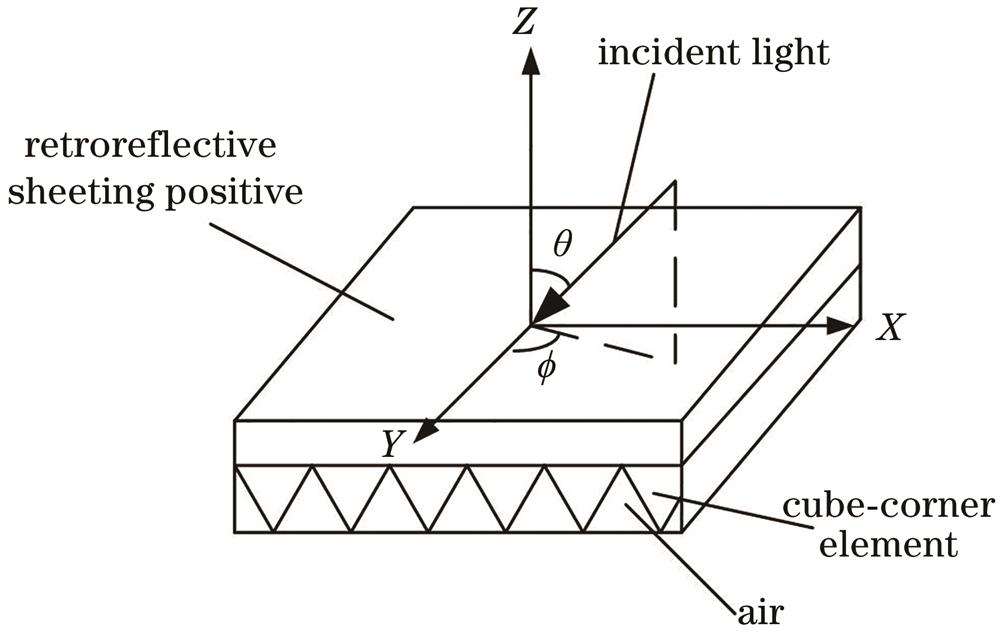
Fig. 1. Spatial distribution of incident light
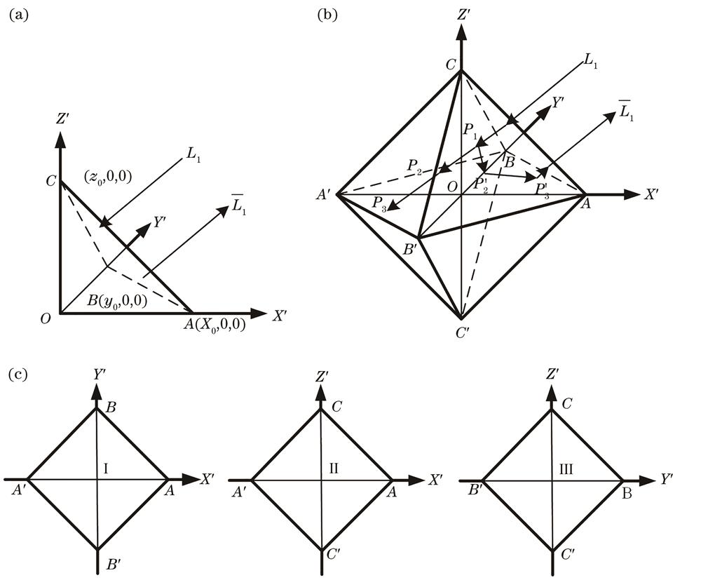
Fig. 2. Principle diagram of retroreflective ray formation. (a) Representation of single CCR element in X'Y'Z' coordinate system; (b) mirror path of retroreflective ray formation; (c) required areas for retroreflective ray formation
Fig. 3. Coordinate system transformation diagram. (a) X'Y'Z' coordinate system of CCR element; (b) X''Y''Z'' coordinate system of CCR element; (c) inclined angle of CCR element
Fig. 4. CCR classification diagram
Fig. 5. Schematic diagram of ray simulation
Fig. 6. CCR array modeling diagram. (a) α = 0°; (b) α = 5°; (c) α = 10°; (d) α = 15°
Fig. 7. Simulation results of retroreflection efficiency of CCR arrays with different α. (a) α = 0°; (b) α = 5°; (c) α = 10°; (d) α = 15°
Fig. 8. Influence of inclination angle on retroreflection efficiency
Fig. 9. Micro morphology of reflective film
Fig. 10. Measurement results of retroreflection coefficient of reflective film
Fig. 11. Results contrast of simulation and testing. (a) θ = 25°; (b) θ = 30°
Fig. 12. Splicing modeling of CCR array with α = 0°
Fig. 13. Retroreflection efficiency of splicing structures of CCR arrays with different refractive indexes. (a) Refractive index is 1.50; (b) refractive index is 1.58
Fig. 14. Comparison of different CCR arrays splicing modeling
Fig. 15. Splicing modeling of CCR arrays with α = 10° and α = -4°
Fig. 16. Simulation results of retroreflection efficiency. (a) CCR array with α = -4°; (b) splicing by CCR arrays with α= 10° and α = -4°; (c) different CCR arrays with ϕ = 0°; (d) different CCR arrays with ϕ = 90°; (e) different CCR arrays with θ= 25°


Set citation alerts for the article
Please enter your email address

© Copyright 2018-2021 | Chinese Laser Press. All Rights Reserved 沪ICP备15018463号-20