
Hao Sui, Xiaorong Gao, Lin Luo, Hongna Zhu, Yunjie Zhong. Finite Element Simulation and Experiment on Interaction of Surface Waves Excited by Laser Point or Line Source with Rail Defects[J]. Laser & Optoelectronics Progress, 2019, 56(8): 081201
- Laser & Optoelectronics Progress
- Vol. 56, Issue 8, 081201 (2019)

Fig. 1. Sectional dimension of rail
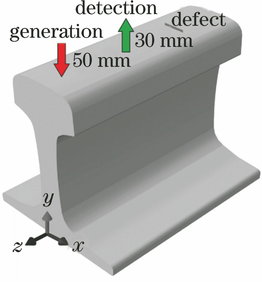
Fig. 2. Model of rail surface under laser irradiation
Fig. 3. Gaussian space and time equivalents of point source and line source. (a) Space equivalent of line source;(b) space equivalent of point source; (c) time equivalent
Fig. 4. Convergence analysis of grids. (a) Grid size of 0.3 mm; (b) grid size of 0.05 mm
Fig. 5. Waveforms in time domain under different grid sizes. (a) 0.3 mm; (b) 0.2 mm; (c) 0.1 mm;(d) 0.075 mm; (e) 0.05 mm
Fig. 6. Ultrasonic speed cloud maps. (a) Point source at 9 μs; (b) point source at 29 μs; (c) line source at 9 μs;(d) line source at 29 μs
Fig. 7. Ultrasonic waveforms in time domain excited by point source and line source. (a) Point source; (b) line source
Fig. 8. Laser ultrasonic detection system
Fig. 9. 60 kg rail sample. (a) Real object; (b) schematic of defects
Fig. 10. Experimental results of ultrasonic waves excited by point source and line source. (a) Point source; (b) line source
Fig. 11. Models of two defects. (a) Model of defect 1;(b) model of defect 3
Fig. 12. Ultrasonic speed cloudmaps for models of two defects. (a) Defect 1, at 3 μs; (b) defect 3, at 9 μs; (c) defect 1, at 18 μs; (d) defect 3, at 29 μs
Fig. 13. Ultrasonic signals in time domain for models of two defects. (a) Simulation signal for defect 1;(b) simulation signal for defect 3; (c) experimental signal for defect 1; (d) experimental signal for defect 3
|
Table 1. Thermophysical parameters of rail materials used in finite element simulation


Set citation alerts for the article
Please enter your email address

© Copyright 2018-2021 | Chinese Laser Press. All Rights Reserved 沪ICP备15018463号-20