• Laser & Optoelectronics Progress
  • Vol. 60, Issue 17, 1714003 (2023)
Weiyi Yuan1, Min Fu1, Zhixian Li1, Zefeng Wang1,2,3, and Zilun Chen1,2,3,*
Author Affiliations
  • 1College of Advanced Interdisciplinary Studies, National University of Defense Technology, Changsha 410073, Hunan , China
  • 2Nanhu Laser Laboratory, National University of Defense Technology, Changsha 410073, Hunan , China
  • 3State Key Laboratory of Pulsed Power Laser Technology, Changsha 410073, Hunan , China
  • show less
    DOI: 10.3788/LOP222312 Cite this Article Set citation alerts
    Weiyi Yuan, Min Fu, Zhixian Li, Zefeng Wang, Zilun Chen. 2 kW Bidirectional Fiber Cladding Power Stripper[J]. Laser & Optoelectronics Progress, 2023, 60(17): 1714003 Copy Citation Text show less
    Surface of corroded optical fiber
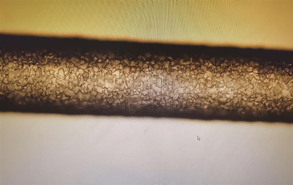
    Fig. 1. Surface of corroded optical fiber
    Relationship between stripping efficiency and corrosion time under different corrosion lengths
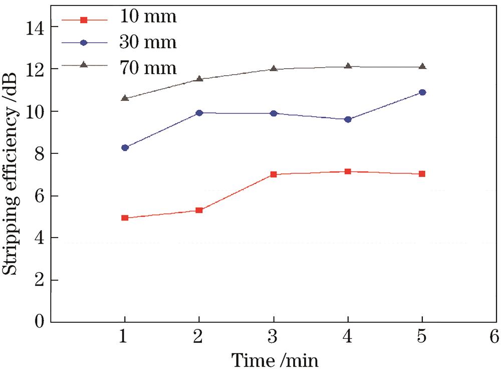
    Fig. 2. Relationship between stripping efficiency and corrosion time under different corrosion lengths
    Corroded optical fiber
    Fig. 3. Corroded optical fiber
    Temperature of CPS#1 with 600 W input power
    Fig. 4. Temperature of CPS#1 with 600 W input power
    Stripping efficiency and temperature test optical path diagram of CPS#1
    Fig. 5. Stripping efficiency and temperature test optical path diagram of CPS#1
    CPS#1 output power, temperature, and stripping efficiency varying with input power
    Fig. 6. CPS#1 output power, temperature, and stripping efficiency varying with input power
    Temperature of CPS#1 with 2 kW input power
    Fig. 7. Temperature of CPS#1 with 2 kW input power
    CPS#1 temperature with reverse input light
    Fig. 8. CPS#1 temperature with reverse input light
    Schematic of bidirectional designed CPS
    Fig. 9. Schematic of bidirectional designed CPS
    Variation of output power with input power for bidirectional optical input
    Fig. 10. Variation of output power with input power for bidirectional optical input
    CPS#2 temperature with forward input
    Fig. 11. CPS#2 temperature with forward input
    CPS#2 temperature with reverse input
    Fig. 12. CPS#2 temperature with reverse input
    Physical drawing of CPS sleeve glass tube
    Fig. 13. Physical drawing of CPS sleeve glass tube
    Schematic of water cooling fixture
    Fig. 14. Schematic of water cooling fixture
    Cross-section drawing of water cooling fixture
    Fig. 15. Cross-section drawing of water cooling fixture
    Physical drawing of water cooling fixture
    Fig. 16. Physical drawing of water cooling fixture
    ParameterPart 1Part 2Part 3
    Corrosion length /mm103030
    Corrosion time /min125
    Table 1. CPS#1 preparation process
    ParameterPart 1Part 2Part 3Part 4Part 5
    Corrosion length /mm1030303010
    Corrosion time /min12521
    Table 2. CPS#2 preparation process