1Wuhan National Laboratory for Optoelectronics and School of Optical and Electronic Information, Huazhong University of Science and Technology, Wuhan 430074, China
Jing Du, Zhiqiang Quan, Kang Li, Jian Wang, "Optical vortex array: generation and applications [Invited]," Chin. Opt. Lett. 22, 020011 (2024)
Copy Citation Text
【AIGC One Sentence Reading】:Optical vortex arrays, with special wavefront structures, have vast applications in various fields. Their generation methods are key, and this review covers their fundamentals, generation techniques, and diverse applications.
【AIGC Short Abstract】:The review discusses optical vortex arrays, highlighting their diverse applications in fields like optical communications and quantum technology. It introduces methods for generating these arrays, such as using diffractive optical elements, metasurfaces, and integrated devices, and explores their uses in various domains. The article concludes with a summary and future research outlook for optical vortex beam arrays.
Note: This section is automatically generated by AI . The website and platform operators shall not be liable for any commercial or legal consequences arising from your use of AI generated content on this website. Please be aware of this.
Abstract
Optical vortex arrays, with their unique wavefront structures, find extensive applications in fields such as optical communications, trapping, imaging, metrology, and quantum. The methods used to generate these vortex beam arrays are crucial for their applications. In this review, we begin with introducing the fundamental concepts of optical vortex beams. Subsequently, we present three methods for generating them, including diffractive optical elements, metasurfaces, and integrated optical devices. We then explore the applications of optical vortex beam arrays in five different domains. Finally, we conclude with a summary and outlook for the research on optical vortex beam arrays.
An optical vortex is a type of optical field structure with unique singular points, resembling vortices in fluids or spiral-shaped galaxies[1]. Optical vortices are primarily divided into two categories, where one involves light fields with phase singularities[2]. In this type of optical vortex, a helical spiral phase factor is present, where represents the topological charge, and stands for the azimuthal angle. Within this optical field structure, photons carry an orbital angular momentum (OAM) of magnitude [3]. Some typical models of optical vortices include Laguerre–Gaussian (LG) modes[4], Ince–Gaussian (IG) modes[5], Bessel beams[6], Mathieu beams[7], circular Airy beams[8] in free space, as well as circularly polarized OAM modes in few-mode/multimode fibers[9–11] or ring core fibers[12–14]. The other kind of optical vortex is characterized by polarization singularity, where the polarization state changes with the variation of the azimuthal angle, also referred to as the polarization vortex or vector vortex[2]. This type of optical vortex exists in various vector or cylindrical vector beams in free space[15–17] and takes the form of eigenmodes in optical fibers[18,19]. Utilizing these characteristics of optical vortices, optical vortices have been applied in various fields such as optical communication[20–24], quantum information[25–29], microscopy/imaging[30–34], optical tweezers[35–39], and metrology[40–44].
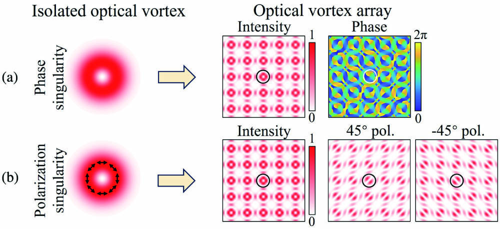
In addition to isolated optical vortices, the arrangement of multiple optical vortices with a specific periodic structure in two or three dimensions can form an optical vortex array, also known as an optical vortex lattice[45]. Figure 1 illustrates a schematic comparison between isolated optical vortices and a 2D optical vortex array with a rectangular lattice. Figure 1(a) shows an optical vortex array assembled by multiple phase singularities with a topological charge number of , where there exists a spiral phase variation of at the center of each doughnut-shaped pattern. Figure 2(a) displays an optical vortex array composed of multiple polarization singularities with radially linear polarization distribution, where the spot shape can be transformed into a two-lobe structure using a polarizer at each optical vortex. In addition to the optical vortex array with a rectangular lattice structure shown in Fig. 1, the lattice structure of optical vortex arrays can also be arranged in triangular[46], hexagonal[47], or even more complex configurations[48]. Each optical vortex in the vortex array can have the same topological charge or different topological charges, and they can even exhibit different polarization states. Compared with isolated optical vortices, an optical vortex array can provide more manipulation of the degree of freedom by controlling the number of optical vortices or the optical lattice structure, which has brought forth more appealing features and can offer a technological research platform in the field of optics[49,50].
Figure 1.Diagram of isolated optical vortices and optical vortex arrays with (a) phase singularity and (b) polarization singularity. Pol, polarizer.
In this review, we first provide a brief introduction to the fundamental concepts and characteristics of optical vortices and optical vortex arrays in the first section. In the second section, we present the methods for generating optical vortex arrays, including classical diffractive optical elements, metasurfaces, and integrated optical devices. The third section discusses the application areas of optical vortex arrays, encompassing optical trapping, optical communications, imaging, metrology, and quantum applications. Finally, we conclude and provide future perspectives on optical vortex arrays.
Sign up for Chinese Optics Letters TOC. Get the latest issue of Chinese Optics Letters delivered right to you!Sign up now
2. Generation of Optical Vortex Array
In this section, we primarily introduce three main methods for generating optical vortex arrays, including classical diffractive optical elements, metasurfaces, and integrated optical devices, as shown in Fig. 2. In the approach using classical diffractive optical elements to generate optical vortex arrays, we mainly discuss the principles and implementation examples of multi-beam interference, holograms, phase plates, and spatial light modulators (SLMs). In the approach using metasurfaces to generate optical vortex arrays, we mainly review several types of metasurfaces, including metal-based metasurfaces based on surface plasmon resonance, dielectric metasurfaces based on Mie resonances, functional metasurfaces composed of multiple layers, and geometric metasurfaces with unit cells arranged in a geometric distribution. In the approach using integrated optical devices to generate optical vortex arrays, we mainly introduce various integrated devices based on different platforms, including femtosecond laser writing, vertical-cavity surface-emitting lasers (VCSELs), and silicon-based integrated devices.
2.1. Classical diffractive optical elements
To generate optical vortex arrays, the most common approach involves using a spatial optical path composed of diffractive optical elements, such as beam splitters, lenses, prisms, and more. These elements create a network of optical vortices through the interference or diffraction of multiple beams. In 2001, Masajada and Dubik proposed a method for generating optical vortex arrays using three-plane wave interference[51]. In this approach, three coherent plane waves with the same frequency and similar amplitude but different directions were used to create multi-beam interference in free space. This interference leads to the formation of triangular grid-like bright and dark fringes within the interference region, as shown in Fig. 3(a). To verify the presence of an optical vortex array within the generated grid-like spots, a fourth coherent plane wave with the same frequency, polarization, and similar amplitude was introduced. This wave was inclined to interfere with the generated optical field. From the interfered light intensity patterns in Fig. 3(a), it can be observed that dark regions within each grid-like spot resulted in fork patterns, confirming the presence of vortex optical fields with topological charge numbers of within each spot’s dark region. The reason for generating optical vortices through three-beam interference lies in the fact that the amplitude vector of the beams becomes zero at certain nodes within the interference region. The argument at these nodes becomes singular, leading to the occurrence of all phases from 0 to in their vicinity.
Figure 3.Generation of optical vortex array using classical diffractive optical elements. (a) Generating optical vortex arrays using three-plane wave interference[51]. (b) Vortex structure of multiple-plane wave interference[54]. Generating optical vortex arrays using (c1) phase plate[56], (c2) helical phase spatial filter[57], and (c3) spatial light modulator[59].
In 2007, Vyas and Senthilkumaran extended the conventional three-beam interference method by proposing an approach based on optimized Michelson and Mach–Zehnder interferometers for generating optical vortex arrays. By replacing the mirrors in the Michelson and Mach–Zehnder interferometers with another set of Michelson or Mach–Zehnder interferometers, real-time adjustment of the period, position, and intensity of the vortex beam array can be achieved[52]. This modification enhances the flexible control of the vortex beam arrays. In the same year, Vyas and Senthilkumaran also utilized three spherical waves with different directions for interference, thereby achieving the generation of an optical vortex array[53]. They also confirmed that the generation of the optical vortex array primarily depends on the phase difference between the beams rather than the phase distribution of the beam fronts. In addition to using three beams of light to generate interference for the production of an optical vortex array, four, five, or even more beams of light can also generate an optical vortex array as long as the sum of the amplitude vectors of all beams is zero at certain nodes[54]. The vortex structure of the optical vortex array produced by the interference of three beams of light consists of parallel lines, whereas the vortex structure of the vortex beam array generated by multiple beams of light is complex, as shown in Fig. 3(b).
In addition to using multi-beam interference to generate an array of vortex beams, holograms or phase plates are another commonly used method for generating optical vortex arrays using diffractive optical elements. Holograms can modulate the complex amplitude of the incident light wave and split it into multiple waves, which then interfere in the far field to create a more complex wavefront structure. Phase plates, on the other hand, can directly modulate the wavefront phase of the incident light beam according to the desired structure of the optical vortex array, thereby generating the vortex beam array directly. For the first time, Soskin and their team employed holograms to generate individual optical vortices, utilizing a fork-shaped grating structure to produce optical vortices with specific topological charge numbers[55]. To generate an array of vortex beams, specialized phase patterns are also required. Kim et al. modulated a fundamental Gaussian beam using a simple first-quadrant phase plate with a phase shift, generating a pair of optical vortices with opposite topological charge numbers in the far field[56], as shown in Fig. 3(c1). The fundamental Gaussian beam has no phase variation in the angular direction, and its Fourier transform yields spatial frequency components only at a topological charge number of 0. However, introducing a phase modulation in the first quadrant of the beam results in a Fourier transform in the angular direction that yields spatial frequency components at non-zero and opposite topological charge numbers, thereby producing a pair of vortex beams. In addition to directly processing the beam in the spatial domain, phase plates can also manipulate the beam in the spatial frequency domain. Guo et al. proposed a method for generating a vortex beam array based on spatial filtering using a spiral phase plate[57], as shown in Fig. 3(c2). An optical beam with a grid pattern and a spiral phase plate were placed in the focal planes before and after the first lens, and the spiral phase plate filtered the grid pattern light in the spatial frequency domain. In the focal plane behind the second lens, convolution was performed between the grid pattern light and the spiral phase plate. The phase singularities of the spiral phase plate transformed each spot of light into a ring, thereby generating a vortex beam array.
Traditional holograms or phase plates, while effective in generating optical vortex arrays, are limited in their flexibility and degrees of freedom due to their fixed spatial distributions. Researchers now primarily use SLMs for generating vortex light arrays. Spatial light modulators are tunable optical devices that modulate the wavefront’s spatial amplitude or phase of a light beam[58]. By changing the voltage applied to the liquid crystal pixel molecules, the angles between the liquid crystal molecules and the electric field vary, resulting in a certain angle between the direction vector of the liquid crystal molecules and the polarization direction of the incident light. This change alters the effective refractive index of the liquid crystal, affecting the optical path length and achieving phase modulation. By loading the required phase pattern or hologram for generating vortex light arrays onto a spatial light modulator and modulating the incident light, the reflected light can be transformed into an optical vortex array. Figure 3(c3) illustrates an example of generating an optical vortex array using an SLM. By loading circularly distributed phase singularities on the SLM and modulating the incident light, the reflected light is transformed into an optical vortex array arranged in a circular pattern[59].
2.2. Metasurfaces
Since conventional optical diffraction components have large volumetric footprints in contradiction to the trend of high integration of optical systems, the generation of optical vortex arrays has gradually evolved toward compact devices. Metasurfaces are complex flat optical elements composed of periodic micro- and nanostructures that allow multi-dimensional modulation of incident light amplitude, phase, and polarization[60]. Therefore, the use of metasurfaces to generate optical vortex arrays can satisfy the demands for modulation flexibility as well as device miniaturization. In 2017, Jin et al. proposed a nano-slit metasurface that can generate multi-channel vortex light with equal energy[61]. Compared to other schemes that modulate the phase to generate optical vortex arrays, the vortex beams carrying higher-order topological charges still have strong scattering energies, producing optical vortex arrays with better energy uniformity. An ultrathin optical vortex array generator with an array of nanoantennas is shown in Fig. 4(a). Careful consideration was given to the geometry and orientation to enable phase and amplitude modulation. The generator produced the desired phase and amplitude profile for the transmitted right-handed circularly polarized (RCP) light when it was illuminated by left-handed circularly polarized (LCP) light. Then, in the far field, the optical vortex array with equal energy could be seen. A three-dimensional (3D) volumetric optical vortex array creation based on light–matter interaction with a high-efficiency dielectric metasurface was studied and experimentally proven by Huang et al.[62], which is shown in Fig. 4(b).
Figure 4.(a) Schematic illustration of the multi-channel vortex beam generation with equal energy using a metasurface[61]. (b) Illustration of the generation and reconstruction procedure of a 3D vortex array based on a dielectric metasurface[62]. (c) Schematic map of metasurface of deflection prisms to generate a non-diffraction optical vortex array[63]. (d) Schematic map of the optical vortex array generator. The green part is the phase map based on the quasi-Talbot effect[64]. (e) Schematic of the generation of wavelength-dependent three-dimensional volumetric OAM beam array based on the geometric metasurface[65]. (f) The sequence of vortex arrays with various topological charges diffracted in the azimuthal direction[66]. (g) Schematic illustration of metasurface-based CVBs generation (g1) and the experimentally obtained CCD images to verify the polarization distribution of the CVBs (g2)[67].
The principles of spiral Dammann zone plates (SDZPs) and Dammann vortex gratings (DVGs) are used to create a 3D optical vortex array with micrometer spatial separation from visible to near-infrared wavelengths. A two-dimensional vortex array in the plane with a uniform energy distribution among the chosen diffraction orders is created by the DVG, which is specifically made for this purpose. This is done by integrating a spiral phase pattern with intrinsic base topological charges of Lx and Ly in the orthogonal directions into the blazing grating. To improve uniformity, each period is divided into equal segments for multilevel continuous phase optimization. An equal-energy optical vortex of a topological charge with the formula mLx + nLy characterizes each diffraction order () in the transverse focal plane. A series of coaxial vortices can be created by the SDZP in the focal volume. A spiral phase structure with an intrinsic base topological charge of Lz is nested within a Dammann zone plate to form an SDZP. Similar to the Dammann grating concept, the light energy can be redistributed uniformly into a number of longitudinal coaxial vortices at the required ordering by adjusting the phase transition points in one period in the radial direction of the SDZP. Moreover, in Ref. [63], Li et al. proposed a functional metasurface of both transparent medium slices and multiple deflection prisms for generating a non-diffracting vortex array, and the schematic is shown in Fig. 4(c). The transmitted waves from the thin, flat metasurface behave analogously to many beams, each with a predetermined propagation direction and phase shift, which create an optical vortex array inside their overlapped region of space when illuminated by plane waves. Lattice type and size can be adjusted by changing the metasurface’s design parameters. This technique can create an optical vortex array with non-diffracting characteristics.
The quasi-Talbot effect can be utilized to create vortex beam arrays since it has a greater multiplication factor than the traditional fractional Talbot effect. Using a plasmonic metasurface created by nano-apertures[64], shows a novel technique for creating optical vortex arrays based on the quasi-Talbot effect of OAM lenses, as shown in Fig. 4(d). The quasi-Talbot effect of OAM lenses is demonstrated through mathematical calculations and theoretical reasoning. The phase map of an OAM lens metasurface device may be generated via geometric phase modulation caused by nano-apertures in predefined azimuth angles. A few OAM lenses can be used to produce multiplying vortex patches in a flexible manner. By adjusting the properties of the OAM lenses, such as their focal length and spatial layout, it is possible to regulate the dispersion of these optical vortex arrays.
Unlike single-wavelength vortex array generation, Jin et al. proposed the creation of single-layered geometric metasurface-based three-dimensional volumetric OAM beams with wavelength-dependent modulation[65]. To control the phase at two distinct wavelengths, the metasurface comprises two separate elliptical nanoantenna. By adjusting the rotation angle of the matching nanoantennas for the circularly polarized incoming light, the entire phase change spanning from 0 to 2π is achieved at each wavelength. Two separate three-dimensional volumetric OAM beams with various operating wavelengths may be combined at the same surface due to the wavelength-dependent phase control of the nanostructures, as illustrated in Fig. 4(e). Two separate three-dimensional volumetric OAM beams are created from the circularly polarized light at wavelengths of 719 nm and 990 nm, respectively, with the opposite helicity to the incident light. The vortex beam array arrangement can also be modulated by the metasurface[66] and investigates and experimentally shows multichannel optical vortex array generators based on angular multiplexing utilizing an ultrathin geometric metasurface, which is shown in Fig. 4(f). A collection of elliptical nanoholes with variable orientations make up the metasurface. The appropriate phase profile for the excited opposite handedness component is produced when a beam of circularly polarized light strikes the nanoholes. Different vortex arrays diffract on the transmission side at different angles, thanks to a properly designed metasurface. Each channel’s vortex array’s topological charge and pattern may be separately determined. Since the illumination angle and the diffraction angle of the vortex array are specifically connected, it is possible to combine new vortex arrays by adjusting the illumination angle of the incident light, greatly enhancing optical information security.
Similar to phase vortices, a CVB beam array can be generated by designing metasurface structures[67]. Figure 4(g1) shows how to create several CVBs from a single dielectric metasurface. LCP and RCP vortex beam arrays are produced by the metasurface. These combine once again to create a variety of CVBs with various polarization distributions. The LCP and RCP vortex beams’ phase differences, due to diffraction, are used in this method to create the correct CVBs by carefully selecting the directions in which the various orders should propagate. The Dammann grating factor in the metasurface’s phase profile controls how many CVBs are produced. This solves the problems with few channels and uneven power distributions. Figure 4(g2) shows the experimental results of the generated CVBs passing through different analyzing polarizers. The metasurface is usable for a wide range of wavelengths since the geometric phase and the phase difference between the RCP and LCP vortex beams at a given order are all wavelength independent. This method also offers a great deal of control over vector fields since it enables the construction of CVBs of various orders and adjusts the rotation of their polarization.
2.3. Integrated optical devices
The generation of optical vortex arrays is essential for almost all interesting applications. Many techniques for generating an optical vortex array have been demonstrated, such as holograms[68], multi-plane-wave interferometers[54], the transformation of the Laguerre–Gaussian mode[69], and liquid crystals[70], which rely on expensive and relatively bulky diffractive optical elements. Very recently, for the sake of integration and miniaturization, integrated photonic devices have been presented and demonstrated to generate in-plane and out-of-plane optical vortex arrays[71–74].
For the in-plane optical vortex array, the output light is the in-plane waveguide mode. Photonic chips using femtosecond laser direct writing have unique advantages owing to the ability to process 3D chips. As shown in Fig. 5(a), an array consisting of many asymmetric directional couplers implements the generation of an optical vortex array[71]. The single asymmetric direction coupler including a standard single-mode waveguide and an OAM waveguide can generate different-order vortex beams. Illustrated in the inset of Fig. 5(a), the OAM waveguide composed of 13 waveguides has a doughnut-shaped cross section. Based on phase matching, first-order and second-order vector vortices both have been generated by tuning the radius of each doughnut-shaped waveguide. Figure 5(b) displays the generated first-order (I, II, III) and second-order (IV, V, VI) vector vortices with the fluctuation of the writing laser energy, including intensity patterns, clockwise spiral interference patterns, and counterclockwise spiral interference patterns. One can see that the asymmetric directional coupler array can achieve a robust generation of an optical vortex array against the fluctuation of the writing laser energy.
Figure 5.Integrated optical devices for generating optical vortex array. (a) An array consisting of many asymmetric direction couplers for generating the in-plane optical vortex array[71]. (b) The generated first-order (I, II, III) and second-order (IV, V, VI) vector vortices with the fluctuation of the writing laser energy, including intensity patterns, clockwise spiral interference patterns, and counterclockwise spiral interference patterns[71]. (c) 8 × 8 spiral phase plate for generating the 8 × 8 out-of-plane optical vortex array[72]. (d) The phase distribution of OAM + 0.5 by the designed spiral phase plate[72]. (e) Three identical microring emitters can form an optical vortex array silicon-integrated emitter to generate an optical vortex array[73]. (f) Near-field intensity patterns and interference patterns of optical vortex array from the microring array[73]. (g) Silicon on-chip optical vortex array emitter with shallow-etched tilt gratings[74]. (h) Simulated phase distribution of the optical vortex array generated by the shallow-etched tilt gratings. The inset is the zoom-in phase distribution of an optical vortex with a topological charge number of −1[74]. (i) Measured intensity distribution of fork patterns by interfering with the generated optical vortex array with a plane wave. The inset shows the zoom-in intensity distribution of a fork-like fringe pattern[74].
For the out-of-plane optical vortex array, the generated optical vortex array is an out-of-plane integrated device. The 2D optical vortex array is generated by growing an spiral phase plate structure on the top of a traditional VCSEL, as shown in Fig. 5(c)[72]. By changing the parameters of a single spiral phase plate, the generated optical vortex array has arbitrary and desired topological charges. The single spiral phase plate can be designed to obtain a fractional optical vortex [see Fig. 5(d)]. In addition, three identical microring emitters can form an optical vortex array silicon-integrated emitter that is coupled to the same access waveguide, as shown in Fig. 5(e)[73]. The specially designed optical vortex microring with angular gratings can extract the OAM beam confined in the whispering gallery modes (WGMs). It is worth mentioning that the radius of the smallest microring is 3.9 µm, which is quite small. Figure 5(f) gives the near-field intensity patterns and interference patterns of the optical vortex array from the microring array, which all show the topological charge number of . The above structures are combined with many single integrated optical vortex emitters to obtain an optical vortex array. In addition, the integrated device relying on multi-plane-wave interference can also be used to generate the optical vortex array. As shown in Fig. 5(g), a simple and compact silicon optical vortex array emitter consisting of shallow-etched tilt gratings is presented to enable the generation of the optical vortex array[74]. The tilt grating can implement flexible light emission with a wide range of directions, which is conducive to three-plane-wave interference. Figure 1(h) shows the simulated phase distribution of the optical vortex array generated by the shallow-etched tilt gratings. From the inset of Fig. 5(h), the zoom-in phase distribution shows the OV with a topological charge number of . Figure 5(i) illustrates the measured intensity distribution of the fork patterns by interfering with the generated optical vortex array with a plane wave. It can be seen that there is a network of fork-like patterns, and each fork pattern corresponds to a phase singularity in the simulated result, verifying the successful generation of the optical vortex array. Further, the light emission of the grating can be improved by a reverse-designed structure[75,76] and a structure with a backside mirror[77].
3. Applications of Optical Vortex Array
In this section, we primarily introduce various applications of optical vortex arrays, focusing on five main areas: optical communication, optical trapping, imaging, metrology, and quantum, as illustrated in Fig. 6. Compared to individual optical vortices, vortex beam arrays consist of multiple vortex beams with a unique spatial grid structure, providing greater flexibility and dimensions for manipulation, thereby introducing some unique characteristics when applied in these fields.
Optical vortices have been widely researched and applied in the field of optical communication. Optical vortices carry OAM, and optical vortices with different topological charge numbers are orthogonal to each other. This characteristic makes them suitable for SDM techniques, effectively increasing the communication capacity of optical communication systems[78]. In addition to using optical vortices as independent channels for communication, the topological charge numbers carried by optical vortices can also be used for information modulation/demodulation[79,80]. Similar to traditional information modulation methods, such as amplitude shift keying, shift keying, or quadrature amplitude modulation that encode information using the amplitude and phase dimensions of the optical field, information modulation based on optical vortices utilizes the OAM dimension for information encoding. Compared to traditional information modulation methods, transmitting data using optical vortices for information modulation offers higher security. This is because optical vortices possess a unique wavefront structure, and eavesdroppers would need to intercept a substantial portion of the optical field along the beam’s propagation path for wavefront demodulation[79]. This would significantly degrade the communication quality, raising suspicion. If eavesdroppers only capture a small portion of the optical field for wavefront demodulation, then the wavefront structure of the vortex beam is disrupted, making it difficult to recover the required topological charge number information.
In addition to individual optical vortices being used for information modulation, optical vortex arrays can also be employed for information encoding/decoding. Compared to individual optical vortices, optical vortex arrays, composed of multiple optical vortices arranged in a grid-like planar distribution, carry a greater amount of information and offer higher modulation flexibility. This has made them a research hotspot in recent years. Li and Wang proposed a communication method for encoding/decoding information using an optical vortex array based on a rectangular grid structure[81], as shown in Fig. 7(a). This optical vortex array in space contains four independent optical vortices, with each optical vortex capable of carrying five or six different OAM values. This allows the optical vortex array to perform information encoding/decoding in a base-125 or base-1296 system. At the receiving end, each optical vortex in the optical vortex array is demodulated using a specially designed complex phase pattern. This complex phase pattern is a two-dimensional fork-shaped grating that can transform the incoming vortex beams into multiple diffraction directions, each having different topological charge numbers. If the topological charge number of the incoming vortex beam matches the topological charge number of a specific diffraction angle, then the corresponding light field will transform into a central bright spot resembling a fundamental mode Gaussian beam. Otherwise, it remains a hollow vortex beam. By determining the position of the fundamental Gaussian mode in space, the topological charge number of the incoming vortex beam can be identified, thereby achieving demodulation. In this scheme, the vortex beam array consists of four optical vortices. Compared to using a single vortex beam for information encoding/decoding, this approach uses only a quarter of the vortex beam types, which is crucial for reducing system complexity and simplifying the demodulation of vortex beams.
Figure 7.Optical communication using optical vortex array. (a) Encoding/decoding using optical vortex array[81]. Hexadecimal encoding/decoding using optical vortex array based on position and topological charge information[82]. (b1) Definition of encoding and (b2) intensity profiles. (c) Encoding/decoding using elliptical vortex beam array[83]. (d) Encoding/decoding using vector beam array[85]. (e) Encoding/decoding using perfect vector beam array[88].
In Ref. [81], the spatial positions and spacing between optical vortices in the optical vortex array are fixed. To increase the amount of information carried per symbol, it is necessary to increase the number of used OAM states. In addition to increasing the number of OAM states, it is also possible to increase the information capacity per symbol by altering the spatial distribution structure of the optical vortex array. Li et al. proposed an information encoding/decoding method for optical vortex arrays based on spatial positions and topological charge numbers[82], as shown in Figs. 7(b1) and 7(b2). This encoding method employs 8 binary bits to encode the spatial positions of the vortex beams, including the inner and outer positions of the vortices and their counterclockwise arrangement sequence. It also uses 16 vortex beams with different OAM values for hexadecimal information encoding. In this scheme, an optical vortex array composed of 4 vortex beams can encode 24 binary bit sequences, significantly improving the encoding efficiency. To further enhance the flexibility and degrees of freedom for information encoding in optical vortex arrays, Liu et al. proposed a method based on elliptical vortex beam arrays[83], as shown in Fig. 7(c).
Elliptical vortex beams are a special case of ordinary vortex beams. Unlike ordinary vortex beams with circularly symmetric field distributions, elliptical vortex beams exhibit anisotropic field distributions at different angular positions and possess a polarization direction. Information can be encoded by changing the rotation angle of the major axis of elliptical vortex beams, thereby increasing the degrees of freedom for encoding. In Ref. [83], a array of elliptical vortex beams was used, with each vortex beam in the array having four different combinations of topological charge numbers. This means that each codeword formed by the elliptical vortex beam array has an information capacity of 64 binary bits, effectively enhancing the communication capacity.
In addition to using the topological charge of optical vortices for information encoding/decoding, another type of vortex beams, namely vector beams with polarization singularities, can also utilize their spatial polarization distribution characteristics for information encoding/decoding. Zhan and Wang employed 16 different vector beams with distinct spatial polarization distributions for information encoding[84]. In comparison to the method of encoding information using topological charge numbers, vector beams can be demodulated using a polarizer without the need for additional phase patterns to transform the vortex beam back into a fundamental Gaussian beam. Wang et al. proposed an information encoding/decoding method based on a array of vector beams[85], as shown in Fig. 7(d). At the transmitter, four linearly polarized lasers are arranged in a rectangular array, and the light from each laser passes through a combined Q-plate, transforming it into a vector beam, thus forming a vector beam array. By employing four different vector beams and four spatial positions, each codeword in this encoding method can carry 8 binary bits of information. The general methods of information encoding/decoding using the topological charge or spatial vector distribution of vortex beams often involve different orders, and vortex beams of different orders have different spot sizes and divergence angles. This can limit their application within finite receiver apertures. To address this issue, the concept of perfect vortex beams or perfect vector beams has been introduced[86,87]. Long et al. proposed a scheme for information encoding/decoding using a perfect vector beam array[88], as shown in Fig. 7(e). They utilized a perfect vector beam array, where each vector beam had 16 different spatial distributions. Each codeword could carry 16 binary bits of information. Since perfect vector beams were employed, vector beams of different orders had the same beam radius, thus avoiding the limitations imposed by finite receiver apertures.
3.2. Trapping
As a key technology to study the motion of objects and their interactions at the micro- and nanoscale, optical tweezers technology has important applications and is widely used in the fields of physics, chemistry, micromechanics, and biomolecular interactions because of its advantages of no contact, no damage, and high accuracy. The manipulation of an object by light relies on the momentum transfer between light and the object. The transfer of linear momentum enables the capture and translation of the object, while the transfer of angular momentum leads to the rotation of the object. In addition, an optical vortex array can capture multiple particles in space at the same time, which opens up the possibility of multi-target manipulation.
The methods for producing many high-quality optical traps in any number of three-dimensional configurations, as well as for dynamically rearranging them under computer control, are proposed in Ref. [89]. This scheme allows for the creation of mixed arrays of traps based on various light modes, such as optical vortices, axial line traps, optical bottles, and optical rotators, in addition to the typical optical tweezers. Multiple colloidal particles may be seen caught on the brilliant edges of a array of vortices in Fig. 8(a). Particles stuck on optical vortices encounter tangential forces due to the helical wavefronts that characterize Laguerre–Gaussian modes. As they travel quickly around the ring, particles caught on a vortex’s brilliant perimeter, like the ones in Fig. 8(a), entrain flowing fluids. Particles trapped on nearby vortices move cooperatively as a result of the hydrodynamic coupling, which also affects movements on individual vortices. By adjusting the topological charges, intensities, and locations of the optical vortices in an array, the resulting fluid flows may be dynamically altered and may be advantageous for microfluidics and lab-on-a-chip applications.
Figure 8.Trapping using optical vortex array. (a) Generated optical vortex array with the same topological charge (a1) and different topological charges (a2). The particles can be rotated by the optical vortex traps (a3)[89]. (b) Experimental results of the optical vortex tweezers with opposite topological charges (b1) and the rotation direction controlling (b2)[68]. (c) The intensity distribution of illuminating the DOE with an LG l = 3 beam to trap a low index particle of suitable diameter[90]. (d) The intensity distribution of HOTA with GPs, OVs, PVs, and Airy beams[92]. (e) Experimental (upper) and theoretical (bottom) typical intensity distributions of different optical vortex arrays with n = 1, 2, 3, 4, 5, 6 at the focal plane[93].
In Ref. [68], Ladavac et al. produced an optical vortex array with different topological charges using the holographic optical tweezer method, in which a single laser beam is divided into numerous independent beams by a computer-generated hologram, each of which may be directed into a different optical trap. Additionally, the same hologram can change each diffracted beam into a helical mode with a uniquely defined topological charge number, . The array of optical vortices, whose focal waists can be seen in Fig. 8(b), is encoded by the phase hologram, . The topological charge of the upper row of the optical vortices is , and the lower row has the opposite helicity, . Thus, the two rows produce torques in opposing directions that may be combined to form a microfluidic pump.
However, the particle with a low refractive index is more difficult to trap and manipulate. To solve this problem[90], a array of Laguerre-Gaussian (LG) trap is used in this instance to remove low index particles from a population, which is shown in Fig. 8(c). Additionally, it has shown how well such arrays capture particles in a dynamic context (relative fluid motion) and as a function of the beam parameters. In order to investigate the particle trapping ability of an optical vortex array, Kuo et al. calculated the optical force of different vortex beams acting on dielectric particles of different sizes. The discrete dipole approximation (DDA) approach is used in Ref. [91] to examine the characteristics of the vortex array laser tweezers based on the Ince–Gaussian modes (IGMs) as they capture dielectric particles. The resulting force applied to the spherical dielectric particles of various sizes located at the IGM-based vortex array laser beam waist is calculated. The number of trapping spots of a structured light, such as an IGM-based vortex laser beam, is dependent on the relationship between the size of the trapped particle and the size of the structured light beam, according to numerical studies. The IGM-based vortex array laser beam tweezers are appropriate for many traps, even if the trapped particle is tiny compared to the beam size of the lasers.
In Ref. [92], any combination of optical traps, such as the Gaussian point (GP), optical vortex (OV), perfect vortex (PV), and Airy beams on the focal plane, has been used to create a hybrid optical trap array (HOTA), as shown in Fig. 8(d). Additionally, each one’s axial location and peak intensity can be separately changed. The energy efficiency of this approach is theoretically investigated, and empirically, distinct micro-manipulations on many particles have been accomplished with the help of HOTA. The energy ratio between several optical traps can be changed to match the demand for optical trapping and manipulation, which is one of the two key distinctions between this approach and the other methods. The second is that it is capable of producing hybrid optical trap arrays made up of various combinations of GP, OV, PV, Airy beams, etc., which increases the flexibility of manipulating particles.
The th-order alternated optical vortex array, which was proposed by Liu et al., is a type of arbitrary order alternated optical vortex array with positive and negative topological charges [93]. It is illustrated in Fig. 8(e). According to the experimental findings, such optical vortex arrays are capable of producing finite square optical arrays with intriguing patterns or flaws close to the focal plane or far-field Fraunhofer region. Meanwhile, there are more brilliant spots () in finite optical arrays when the topological charge () increases. Potential uses for this optical vortex array include particle entrapment and experimental realizations of cutting-edge optical arrays for the interaction of unique optical lattices with atoms (or molecules, ions, micro- or nanoparticles), among other things.
3.3. Imaging
Optical imaging creates finely detailed pictures of actual or virtual things using light. It is one of the oldest methods used by humans from the beginning of time and is frequently utilized in sensing, information storage, and medical observation, among other things. Even though today’s society expects optical imaging applications with ever-increasing precision, quality, and capacity, their exploitable potential from the instrumentation side of the traditional optical imaging approaches is virtually exhausted. An important benefit of optical vortex array imaging technology is the multi-channel transmission, processing, and encryption of images. Unlike the wavelength and polarization divisions of light, the OAM of light can be used as an information carrier for holography because its helical wavefront can provide more independent physical modes. In Ref. [94], Fang et al. proposed that high-order OAM beams may be used to create multi-bit OAM-multiplexing holograms that can encrypt all-optical data with previously unheard-of levels of security. To demonstrate the theory, a 10-bit OAM multiplexing hologram is created by encoding the ten digits of the Arabic numerals 0 to 9 in turn using ten high-order OAM modes with helical mode indexes ranging from to 50 [Fig. 9(a1)]. Meanwhile, they illustrated the holographic encoding of independent OAM information channels for the multiplexed display, which is shown in Fig. 9(a2). Ref. [95] demonstrates the optical vortex array for image transfer in free-space link. Zhu et al. provided a unique design approach to build vortex array phase gratings (VAPGs) for variable vortex array production and used the suggested VAPGs to implement multi-dimensional space/mode/amplitude coding/decoding, as shown in Fig. 9(b1). They successfully created vortex arrays with various mode states and relative power in the tests by building VAPGs with various parameter settings and loading them onto a single spatial light modulator (SLM). Additionally, an pixels image with 256 gray-scale levels is also communicated in free space to clearly illustrate the data transmission capability of the proposed high-dimensional space/mode/amplitude data coding/decoding [Fig. 9(b2)].
Figure 9.Optical vortex array imaging. (a) OAM code chart consisting of ten high-order OAM modes that could be used to reconstruct the ten OAM-dependent digits based on the OAM ciphertext (a1), and the reconstruction of the complete Sydney Opera House image based on the four decoding OAM beams (a2)[94]. (b) Examples of recorded vortex array intensity patterns for space/mode/amplitude coding/decoding (b1) and the transmitted and received grayscale images using the proposed multi-dimensional space/mode/amplitude data coding/decoding scheme (b2)[95]. (c) The plaintext and decrypted image using the vortex beam’s encryption. The bottom images are the decryption keys in three channels[96]. (d) Principle of the elliptic perfect optical vortex orbital angular momentum selective holography[97]. (e) Schematic illustration of a metasurface polarization hologram, projecting a polarization pattern encoding an RGB image[98]. (f) Schematic illustration of the overall multi-freedom metasurface and the realization of frequency multiplexing by a k-space engineering technique, leading to a full-color complex-amplitude vectorial meta-hologram[99].
Similarly, the orthogonal property possessed by optical vortex beams is of great advantage in image encryption. Kumar et al. illustrated an image encryption method employing a light beam that has rows and columns of spatially isolated orthogonal optical vortex states[96]. It allows for high-dimensional encoding and reduces quality deterioration. Figure 9(c) shows the experiment to verify the encryption scheme with input plaintext in the form of an 8-bit color image. It consists of elements. The bottom image shows the keys for decoding each color channel individually. In order to extend the tunable dimensions of the vortex optical encryption, Zhang et al. suggested and put into practice in an experiment to use elliptic perfect optical vortex orbital angular momentum multiplexed holography[97]. Investigations into the mode selectivity of ellipticity and rotation angle show that those variables can be employed as extra encoded degrees of freedom for holographic multiplexing. A four-dimensional multiplexed holography can be produced using the topological charge, scaling factor, rotation angle, and ellipticity in combination, as shown in Fig. 9(d). Optical vortex beams with different elliptical ratios can also be used for holographic imaging. Arbadi et al. proposed a scheme that the electric field vector is controlled independently on each point of the mask[98]. The holograms project vectorial images in which the data are stored in the state of polarization. This demonstrates that the metasurfaces are capable of storing and projecting color image data in the polarization state of a monochromatic hologram using a modified Gerchberg–Saxton algorithm and arbitrary color image red-green-blue data converted to Stokes parameters, as shown in Fig. 9(e). Furthermore, frequency multiplexing is further implemented via a k-space engineering method, and a multi-freedom metasurface is created that can concurrently and independently modify phase, polarization, and amplitude[99]. The multi-freedom metasurface seamlessly combines the geometric Pancharatnam–Berry phase and the detour phase, both of which are frequency independent. As a consequence, it permits the creation of complex-amplitude vectorial holograms at multiple frequencies using the same design approach without the need for difficult nanostructure searches of significant geometric factors. Based on this idea, full-color complex-amplitude vectorial meta-holograms are experimentally produced in the visible with a metal-insulator-metal architecture, as shown in Fig. 9(f).
3.4. Metrology
Traditional metrology approaches mostly rely on two-beam interferometry and phase-shifting interferometry[100]. For the two approaches, interference fringes are used to display the metrology results of modified objects. However, the strong scattering or strong absorption or the introduction of systematic error causes poor contrast resolution and therefore is detrimental to accurate measurement[101]. To overcome this problem, a different metrology method using a uniform lattice of optical vortices is present to measure the phase[102], local phase gradients[103], and angular velocity vectors[104].
The phase method using a three-wave-interference optical vortex array is presented to restore the phase of the input wave field[102]. Figures 10(a) and 10(b) show the experimental setup of a three-beam vortex interferometer and the experimentally measured three-beam interference pattern, respectively. When perturbation of the input wave field from the modified objects distorts the optical vortex array, the phase of the exit surface of the object can be determined by the lateral displacement of the vortex[102], since the lateral displacement of the vortex is proportional to the phase shift of the object wave. The exit surface is the plane in which the exit wave travels after passing through the object. Figure 10(c) displays the unwrapped phase profile of the spherical lens using the three-beam vortex interferometer, which indicates there is a good match between the lens profile and the fitted curve. Moreover, the absorbing object (such as the wing of a common house fly) also is used to demonstrate experimentally the phase method using a three-wave-interference optical vortex array.
Figure 10.Metrology by using optical vortex array. (a) Experimental setup of a three-beam vortex interferometer[102]. (b) Experimentally measured three-beam interference pattern[102]. (c) Unwrapped phase profile of the spherical lens using the three-beam vortex interferometer. The solid and dashed curves correspond to the experimental data and the fitted curve, respectively[102]. (d) Experimental setup including a He-Ne laser and a 3-arm Mach–Zehnder interferometer for generating three-beam optical vortex arrays[103]. (e) Experimentally measured phase gradient resulting from the lens specimen[103]. (f) Horizontally averaged vertical phase gradient of the single-mode fiber measurement by using optical vortex array and deterministic in-line holography[103]. (g) Concept of partially coherent angular velocity measurement using optical vortex array[104]. (h), (i) Experimental curves of the relationship between measured frequency shifts and real angular velocities of objects for (h) the three-hole object and (i) the rectangular object[104].
A differential form of singularity is developed to directly measure the phase gradient using optical vortex arrays in non-diffracting or far-field structured illumination[103]. Theoretical analysis shows that the propagation-induced transverse optical flow of optical vortex arrays is proportional to the phase (amplitude) gradient in the focal variation. Figure 10(d) depicts an experimental setup including a He-Ne laser and a 3-arm Mach–Zehnder interferometer for generating three-beam optical vortex arrays of phase vortices and intensity gradient singularities. When a plano-convex lens is used as the measurement sample, the phase gradient is quantified to estimate the focal length to within 1% standard deviation. In addition, it is consistent between the measured vector field and the vector field of the sphere. Figure 10(e) shows the optical vortex array measurements of the phase gradient for the plano-convex lens. When using a single-mode fiber as the test sample, one can see that the vortex array method is sensitive to small changes in refraction. Therefore, based on the nature of local measurements and high precision, the singularity approach should be conducive to slowly varying and subtle specimen-induced gradients.
An optical vortex array can also be applied in an angular velocity measurement method, as shown in Fig. 10(g)[104]. Compared to the previous rotational Doppler velocimetry, this method can relax the strictly aligned requirement between the rotational axes of the targets and the source center, showing a strong anti-interference ability. In addition, the velocity measurement method can measure objects whose dimensions can be as small as 0.6 times the Rayleigh limit. Figures 10(h) and 10(i) illustrate the experimental curves of the relationship between the measured frequency shifts and the real angular velocities of objects for the three-hole object [Fig. 10(h)] and the rectangular object [Fig. 10(i)]. One can see that the ultrahigh-precision and high-accuracy angular velocity vectors (both magnitude and direction) can be measured by using the beat frequency to flexibly control the upturn or downturn of the frequency shift. The scheme can implement the measurement of an ultralow (0.001 r/s) to ultrahigh range (0.1 r/s) of rotational velocity ranging.
3.5. Quantum
The application of optical vortex array in quantum experiments is also a topic of great concern[105–107]. Fractional half-quantum vortices can be dynamically created in Bose–Einstein condensates of sodium atoms[108]. The simulated result shows that both individual half-quantum vortex arrays can be created in rotating optical traps with an additional pulsed magnetic trapping potential, as shown in Figs. 11(a) and 11(b). The square half-quantum vortex arrays always embed a distinct periodically modulated spin-density-wave spatial structure. Additionally, the Talbot effect of optical vortex arrays with single photons is demonstrated and analyzed. The Talbot effect is a self-imaging effect that occurs with the propagation of periodic structural waves[109]. Figure 11(c) shows that when the beam propagates along , the simulated intensity distributions in both the xy- and yz-planes with and without the initial phase verify the Talbot effect of the optical vortex array at a single photon state. It can be observed that the transverse intensity pattern at fractional Talbot distances (zTs) is determined by the initial phase profile and the optical vortex phase structure leads to an asymmetry between the intensity distribution at the propagation distance {zT/8, zT/4, 3zT/8} and {7zT/8, 3zT/4, 5zT/8}. Figure 11(d) presents the intensity distributions of an optical vortex array at fractional Talbot distances with the between simulation, single photon, and diode laser images. The well-matched intensity distributions demonstrate the robustness of the Talbot effect. Therefore, the obtained results are a powerful addition to the toolbox of optical vortex arrays in the quantum field, further leveraging quantum communication and quantum image advantages.
Figure 11.Quantum based on optical vortex array. (a) Creation of a triangular integer-optical vortex array when the rotating optical trap is t = 1600 ms[108]. (b) Different half-quantum vortex arrays with an additional pulsed magnetic trapping potential, as various condensate densities evolve[108]. (c) Simulated intensity distributions in both the xy- and yz-planes with and without the initial phase when the beam propagates along z[109]. (d) Intensity distributions of optical vortex array at fractional Talbot distances with the between simulation, single photon, and diode laser images[109].
In this review, we primarily introduced the fundamental concepts of optical vortex arrays and reviewed their current research status, including the main methods of generating optical vortex arrays and their applications. Currently, the most widely used approach for generating optical vortex arrays is based on diffractive optical elements. This is because this approach offers high efficiency and low energy consumption in generating optical vortex arrays. It is also convenient to set up optical paths in the laboratory using diffractive optical elements. However, this approach is not suitable for practical applications due to the large space requirements of diffractive optical elements, the need for long diffraction distances for the beams, and the high alignment requirements between different optical elements. The method of multi-plane wave interference can be used to generate large-scale arrays of optical vortex beams and tune the characteristics of the optical field. However, this method requires multiple interference structures and has a complex optical system. Tuning the optical field also relies on the mechanical control of the optical elements, resulting in slow speed and limited flexibility. Methods based on holograms and phase plates to generate arrays of optical vortex beams have simpler optical paths. However, the structures of holograms and phase plates are fixed, and they cannot tune the generated optical field. Methods for generating arrays of optical vortex beams based on SLMs offer higher flexibility by loading different phase patterns on liquid crystal displays. However, due to limitations in the refresh rate of liquid crystal displays, it is challenging to achieve high-speed optical field control with this method. To effectively reduce the size of the devices for generating arrays of optical vortex beams, enhancing their flexibility, and increasing control speed, metasurfaces and integrated optical devices have gradually become research hotspots. The method based on metasurfaces for generating arrays of optical vortex beams allows for more precise and complex spatial control of the optical field’s amplitude, phase, and polarization dimensions at sub-wavelength scales. However, this method still faces challenges such as material absorption, control efficiency, and a lack of effective tunable solutions, which limit its practical applications. The method of generating optical vortex beam arrays based on integrated optical devices can effectively reduce device size and achieve relatively high-speed optical field control. However, it still faces challenges such as high losses and poor optical field quality. The various challenges associated with the generation methods of these optical vortex beam arrays are the primary obstacles in various application domains. In the field of optical communication, current methods for generating optical vortex beam arrays mainly rely on SLM, which has a refresh rate of only a few tens of hertz, making it inadequate compared to traditional information modulation rates. In optical trapping applications, a precise and high-degree of control optical vortex beam is required for manipulating small particles, presenting significant challenges for existing optical vortex beam array generation methods. In the field of imaging, optical vortex beam arrays are primarily used for image encryption, demanding high scalability, control flexibility, and speed. In optical metrology and quantum information, there are stringent requirements on the optical spot quality of generated optical vortex beam arrays.
In the future, the generation methods of optical vortex beam arrays are expected to evolve towards miniaturization, high flexibility, fast control, low power consumption, and reconfigurability. Solutions based on metasurfaces and integrated photonic devices are likely to be the future trends. Given the high degree of wavefront control flexibility offered by metasurfaces, the combination of multiple layers of metasurfaces with adjustments in their relative positions may potentially achieve high beam quality and flexible tuning[110]. For integrated photonic devices, the heterogeneous integration of semiconductor lasers, integrated optical amplifiers, and multidimensional optical field control elements onto a single chip holds the promise of generating high-power, high-speed, and highly flexible optical vortex beam arrays[111,112]. On the other hand, a low-cost scheme for generating a optical vortex array may also significantly expand the feasibility of its applications. In Ref. [113], the authors employed a binary mask based on a gradually widening Fermat spiral slit to generate a high-quality single-beam optical vortex beam. This binary mask can be directly printed on a transparent slide, substantially reducing manufacturing costs compared to traditional diffractive optical elements, metasurfaces, and integrated photonics devices. If this single Fermat spiral slit is extended into an array based on Fermat spiral slits, then it holds the potential for achieving low-cost, high-quality optical vortex beam generation. Furthermore, the use of optical vortex arrays may potentially introduce new characteristics in applications. In free-space optical communication systems, spatial diversity techniques can be employed to compensate for channel fading effects induced by atmospheric turbulence[114]. Spatial diversity involves simultaneously transmitting and receiving the same data information through multiple spatially separated apertures, with each beam experiencing different channel transmission conditions. The total received optical power fluctuation in such a system is smaller than the optical power fluctuation for a single aperture, provided that the spot size of each beam in the spatial diversity system is the same as the spot size in a single-aperture system. In addition to employing spatially separated apertures for spatial diversity, multiple orthogonal optical vortex modes can also be used for spatial diversity[115]. In communication systems that utilize optical vortex arrays for information encoding/decoding, the optical vortex array can be considered as a spatial diversity system with multiple spatially separated transmitting and receiving apertures. Compared to using a single vortex beam for information encoding/decoding, the use of an optical vortex array is expected to reduce the power fluctuations at the receiving end caused by atmospheric turbulence. Theoretically, the more vortex beams in the array, the more pronounced the compensation effect for atmospheric turbulence[114].
[58] G. Lazarev, A. Hermerschmidt, S. Krueger et al. LCOS spatial light modulators: trends and applications. Optical Imaging and Metrology: Advanced Technologies, 1(2012).
[78] J. Wang, S. Li, M. Luo et al. N-dimentional multiplexing link with 1.036-Pbit/s transmission capacity and 112.6-bit/s/Hz spectral efficiency using OFDM-8QAM signals over 368 WDM pol-muxed 26 OAM modes. European Conference and Exhibition on Optical Communication (ECOC), Mo.4.5.1(2014).
 AI Video Guide
  AI Picture Guide
 AI One Sentence