
Jing Du, Zhiqiang Quan, Kang Li, Jian Wang, "Optical vortex array: generation and applications [Invited]," Chin. Opt. Lett. 22, 020011 (2024)
- Chinese Optics Letters
- Vol. 22, Issue 2, 020011 (2024)
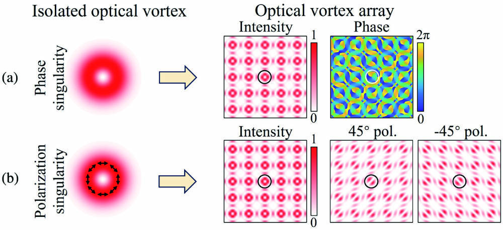
Fig. 1. Diagram of isolated optical vortices and optical vortex arrays with (a) phase singularity and (b) polarization singularity. Pol, polarizer.

Fig. 2. Methods for generation of optical vortex array.
Fig. 3. Generation of optical vortex array using classical diffractive optical elements. (a) Generating optical vortex arrays using three-plane wave interference[51]. (b) Vortex structure of multiple-plane wave interference[54]. Generating optical vortex arrays using (c1) phase plate[56], (c2) helical phase spatial filter[57], and (c3) spatial light modulator[59].
Fig. 4. (a) Schematic illustration of the multi-channel vortex beam generation with equal energy using a metasurface[61]. (b) Illustration of the generation and reconstruction procedure of a 3D vortex array based on a dielectric metasurface[62]. (c) Schematic map of metasurface of deflection prisms to generate a non-diffraction optical vortex array[63]. (d) Schematic map of the optical vortex array generator. The green part is the phase map based on the quasi-Talbot effect[64]. (e) Schematic of the generation of wavelength-dependent three-dimensional volumetric OAM beam array based on the geometric metasurface[65]. (f) The sequence of vortex arrays with various topological charges diffracted in the azimuthal direction[66]. (g) Schematic illustration of metasurface-based CVBs generation (g1) and the experimentally obtained CCD images to verify the polarization distribution of the CVBs (g2)[67].
Fig. 5. Integrated optical devices for generating optical vortex array. (a) An array consisting of many asymmetric direction couplers for generating the in-plane optical vortex array[71]. (b) The generated first-order (I, II, III) and second-order (IV, V, VI) vector vortices with the fluctuation of the writing laser energy, including intensity patterns, clockwise spiral interference patterns, and counterclockwise spiral interference patterns[71]. (c) 8 × 8 spiral phase plate for generating the 8 × 8 out-of-plane optical vortex array[72]. (d) The phase distribution of OAM + 0.5 by the designed spiral phase plate[72]. (e) Three identical microring emitters can form an optical vortex array silicon-integrated emitter to generate an optical vortex array[73]. (f) Near-field intensity patterns and interference patterns of optical vortex array from the microring array[73]. (g) Silicon on-chip optical vortex array emitter with shallow-etched tilt gratings[74]. (h) Simulated phase distribution of the optical vortex array generated by the shallow-etched tilt gratings. The inset is the zoom-in phase distribution of an optical vortex with a topological charge number of −1[74]. (i) Measured intensity distribution of fork patterns by interfering with the generated optical vortex array with a plane wave. The inset shows the zoom-in intensity distribution of a fork-like fringe pattern[74].
Fig. 6. Applications of optical vortex array.
Fig. 7. Optical communication using optical vortex array. (a) Encoding/decoding using optical vortex array[81]. Hexadecimal encoding/decoding using optical vortex array based on position and topological charge information[82]. (b1) Definition of encoding and (b2) intensity profiles. (c) Encoding/decoding using elliptical vortex beam array[83]. (d) Encoding/decoding using vector beam array[85]. (e) Encoding/decoding using perfect vector beam array[88].
Fig. 8. Trapping using optical vortex array. (a) Generated optical vortex array with the same topological charge (a1) and different topological charges (a2). The particles can be rotated by the optical vortex traps (a3)[89]. (b) Experimental results of the optical vortex tweezers with opposite topological charges (b1) and the rotation direction controlling (b2)[68]. (c) The intensity distribution of illuminating the DOE with an LG l = 3 beam to trap a low index particle of suitable diameter[90]. (d) The intensity distribution of HOTA with GPs, OVs, PVs, and Airy beams[92]. (e) Experimental (upper) and theoretical (bottom) typical intensity distributions of different optical vortex arrays with n = 1, 2, 3, 4, 5, 6 at the focal plane[93].
Fig. 9. Optical vortex array imaging. (a) OAM code chart consisting of ten high-order OAM modes that could be used to reconstruct the ten OAM-dependent digits based on the OAM ciphertext (a1), and the reconstruction of the complete Sydney Opera House image based on the four decoding OAM beams (a2)[94]. (b) Examples of recorded vortex array intensity patterns for space/mode/amplitude coding/decoding (b1) and the transmitted and received grayscale images using the proposed multi-dimensional space/mode/amplitude data coding/decoding scheme (b2)[95]. (c) The plaintext and decrypted image using the vortex beam’s encryption. The bottom images are the decryption keys in three channels[96]. (d) Principle of the elliptic perfect optical vortex orbital angular momentum selective holography[97]. (e) Schematic illustration of a metasurface polarization hologram, projecting a polarization pattern encoding an RGB image[98]. (f) Schematic illustration of the overall multi-freedom metasurface and the realization of frequency multiplexing by a k-space engineering technique, leading to a full-color complex-amplitude vectorial meta-hologram[99].
Fig. 10. Metrology by using optical vortex array. (a) Experimental setup of a three-beam vortex interferometer[102]. (b) Experimentally measured three-beam interference pattern[102]. (c) Unwrapped phase profile of the spherical lens using the three-beam vortex interferometer. The solid and dashed curves correspond to the experimental data and the fitted curve, respectively[102]. (d) Experimental setup including a He-Ne laser and a 3-arm Mach–Zehnder interferometer for generating three-beam optical vortex arrays[103]. (e) Experimentally measured phase gradient resulting from the lens specimen[103]. (f) Horizontally averaged vertical phase gradient of the single-mode fiber measurement by using optical vortex array and deterministic in-line holography[103]. (g) Concept of partially coherent angular velocity measurement using optical vortex array[104]. (h), (i) Experimental curves of the relationship between measured frequency shifts and real angular velocities of objects for (h) the three-hole object and (i) the rectangular object[104].
Fig. 11. Quantum based on optical vortex array. (a) Creation of a triangular integer-optical vortex array when the rotating optical trap is t = 1600 ms[108]. (b) Different half-quantum vortex arrays with an additional pulsed magnetic trapping potential, as various condensate densities evolve[108]. (c) Simulated intensity distributions in both the xy- and yz-planes with and without the initial phase when the beam propagates along z[109]. (d) Intensity distributions of optical vortex array at fractional Talbot distances with the between simulation, single photon, and diode laser images[109].


Set citation alerts for the article
Please enter your email address

© Copyright 2018-2021 | Chinese Laser Press. All Rights Reserved 沪ICP备15018463号-20