• Laser & Optoelectronics Progress
  • Vol. 60, Issue 11, 1106017 (2023)
Qun Hao1,2,3, Bin Han1, Ao Yang4, Long Liang1..., Honglin Chen5 and Jie Cao1,2,*|Show fewer author(s)
Author Affiliations
  • 1School of Optics and Photonics, Beijing Institute of Technology, Beijing 100081, China
  • 2Yangtze Delta Region Academy of Beijing Institute of Technology, Jiaxing, Jiaxing 314003, Zhejiang, China
  • 3Changchun University of Science and Technology, Changchun 130022, Jilin, China
  • 4Beijing Huahang Radio Measurement Institute, Beijing 100013, China
  • 5School of Mechanical Engineering, Shandong University of Technology, Zibo 255000, Shandong, China
  • show less
    DOI: 10.3788/LOP231287 Cite this Article Set citation alerts
    Qun Hao, Bin Han, Ao Yang, Long Liang, Honglin Chen, Jie Cao. Spatial Variable Resolution Scanning Three-Dimensional Reconstruction Imaging[J]. Laser & Optoelectronics Progress, 2023, 60(11): 1106017 Copy Citation Text show less
    Schematic diagram of variable resolution scanning. (a) Large-field low resolution scanning; (b) high resolution scanning of local area
    Fig. 1. Schematic diagram of variable resolution scanning. (a) Large-field low resolution scanning; (b) high resolution scanning of local area
    Flow chart of variable resolution scanning
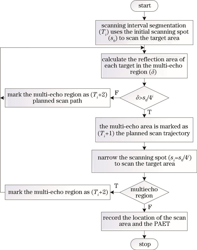
    Fig. 2. Flow chart of variable resolution scanning
    Multi echo region judgment. (a) Target region; (b) (c) schematic diagrams of scanning echo signal
    Fig. 3. Multi echo region judgment. (a) Target region; (b) (c) schematic diagrams of scanning echo signal
    Multi echo region demarcation. (a) Target region; (b) region echo
    Fig. 4. Multi echo region demarcation. (a) Target region; (b) region echo
    Construction of experimental system. (a) Composition of the experimental system; (b) system shooting scenes; (c) target to be measured
    Fig. 5. Construction of experimental system. (a) Composition of the experimental system; (b) system shooting scenes; (c) target to be measured
    Low resolution acquisition and multiple echoes of full field of view scene. (a) depth image with 5 pixel × 5 pixel; (b) multi-echo region
    Fig. 6. Low resolution acquisition and multiple echoes of full field of view scene. (a) depth image with 5 pixel × 5 pixel; (b) multi-echo region
    Target region image and echo. (a) Reconstructed depth image of the target area with 6 pixel × 4 pixel; (b) echoes of each sub-region in the target region scanning
    Fig. 7. Target region image and echo. (a) Reconstructed depth image of the target area with 6 pixel × 4 pixel; (b) echoes of each sub-region in the target region scanning
    Super resolution depth map of the target region with 120 pixel × 80 pixel. (a) Distance image; (b) three-dimensional (3D) image
    Fig. 8. Super resolution depth map of the target region with 120 pixel × 80 pixel. (a) Distance image; (b) three-dimensional (3D) image
    Target region. (a) Measured target area; (b) relative position of the target
    Fig. 9. Target region. (a) Measured target area; (b) relative position of the target
    Experimental results. (a) High resolution scanning reconstruction of 3D images; (b) low resolution scanning reconstruction of 3D images; (c) high resolution scanning reconstruction depth map with 18 pixel × 18 pixel; (d) high resolution scanning reconstruction depth map with 9 pixel × 9 pixel; (e) depth map of the target area in Fig.10 (c); (f) 4 times the upper sampling depth map of the target area in Fig.10 (d); (g) depth map of the target region super-resolution reconstruction in Fig.10 (d)
    Fig. 10. Experimental results. (a) High resolution scanning reconstruction of 3D images; (b) low resolution scanning reconstruction of 3D images; (c) high resolution scanning reconstruction depth map with 18 pixel × 18 pixel; (d) high resolution scanning reconstruction depth map with 9 pixel × 9 pixel; (e) depth map of the target area in Fig.10 (c); (f) 4 times the upper sampling depth map of the target area in Fig.10 (d); (g) depth map of the target region super-resolution reconstruction in Fig.10 (d)
    Distance error distribution of reconstructed depth image in target region. (a) Low resolution reconstruction; (b) high resolution reconstruction
    Fig. 11. Distance error distribution of reconstructed depth image in target region. (a) Low resolution reconstruction; (b) high resolution reconstruction
    ParameterHigh resolution scanningLow resolution scanning
    Scanning field of view5.15°×5.15°5.15°×5.15°
    Spot diameter50 mm100 mm
    Scanning number18×189×9
    Scanning speed1(°)/s1(°)/s
    Table 1. Scanning parameters in the experiment
    Qun Hao, Bin Han, Ao Yang, Long Liang, Honglin Chen, Jie Cao. Spatial Variable Resolution Scanning Three-Dimensional Reconstruction Imaging[J]. Laser & Optoelectronics Progress, 2023, 60(11): 1106017
    Download Citation