Fig. 1. Schematic of a typical few-mode fiber communication system with strong mode coupling
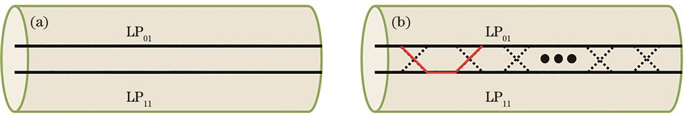
Fig. 2. Schematic of a two-mode fiber transmitting LP01 and LP11 modes, two parallel lines represent two modes. (a) Ideal two-mode fiber transmitting two orthogonal modes; (b) a real fiber that has distributed crosstalk
Fig. 3. Schematic of DMD in a few-mode fiber transmitting three modes (LP01, LP11a, and LP11b)
Fig. 4. Schematic of segmentations of few-mode fiber modeling, transmitting modes
Fig. 5. Typical MIMO TDE structure
Fig. 6. Typical MIMO FDE structure
Fig. 7. System structure of a few-mode fiber with strong coupling system based on MIMO TDE
[24] Fig. 8. System bit error rate and optical power mapping
[24]. (a) First data set with suboptimal condition, and the filter tap is 120; (b)(c) second data set with optimized coupling condition, the filter taps are 120 and 80, respectively
Fig. 9. MDM system with ANN equalizer
[74] Fig. 10. Impulse response of the channel. (a) Input channel; (b) target channel; (c) output channel
[74] Fig. 11. MDM system based on DLNN
[75] Fig. 12. Structure of DLNN
[75] Fig. 13. BER performance of DLNN, ZF, and SDR-RBR
[75] Fig. 14. MDM system architecture with STC
[27] Fig. 15. BER performance of STC compensating MDL under strong coupling
[27]. (a) With STC; (b) with multi-block STC
Fig. 16. U-PIC method compensates MDL experiment. (a) Experimental structure; (b) comparison of transmission distance and spatial multiplicity
[70] Fig. 17. System algorithm architecture with ML
[32] Fig. 18. Performance comparison of ML algorithm under different gain differences
[32]. (a) 0.5 dB; (b) 1 dB; (c) 2 dB
| Algorithm | Convergence speed | Performance | Complexity |
|---|
| LMS | Slow | Large steady-state error(channel related) | Low | | RLS | Fast | Small steady-state error(resistant to noise) | Middle | | VRLS | Fast | Small steady-state error(resistant to noise) | High |
|
Table 1. Comparison of three algorithms for taps update
| Year | Reference | Research institute | Core× mode | Distance /km | Span length /km | Data rate(Gb/s/mode/core/λ) | MIMO taps and types |
|---|
| 2011 | Ref.[52] | University of Melbourne | 1×2 | 4.5 | 4.5 | 107 | — | | 2011 | Ref.[53] | Bell Labs | 1×2 | 40 | 40 | 112 | 9-15 TDE | | 2011 | Ref.[54] | Bell Labs | 1×3 | 10 | 10 | 112 | 20-100 TDE | | 2011 | Ref.[24] | Bell Labs | 1×3 | 33 | 33 | 112 | 80-120 TDE | | 2011 | Ref.[55] | NEC Labs | 1×3 | 50 | 50 | 112 | 301 TDE | | 2011 | Ref.[56] | Bell Labs | 1×5 | 40 | 40 | 112 | — | | 2012 | Ref.[57] | Bell Labs | 1×3 | 96 | 96 | 80 | 120 TDE | | 2012 | Ref.[58] | NEC Labs | 1×3 | 85 | 85 | 112 | 481 TDE | | 2012 | Ref.[59] | Bell Labs | 1×3 | 1200 | 30 | 80 | 400 TDE | | 2012 | Ref.[60] | Bell Labs | 1×3 | 209 | 209 | 80 | 400 TDE | | 2012 | Ref.[61] | Eindhoven University of Technology | 1×3 | 119 | 119 | 256 | 401 TDE | | 2012 | Ref.[62] | Bell Labs | 1×6 | 130 | 65 | 80 | 400-600 TDE | | 2013 | Ref.[63] | Bell Labs | 1×6 | 177 | 59 | 160 | 800 FDE | | 2014 | Ref.[64] | NEC Labs | 1×3 | 500 | 50 | 76 | 511 TDE | | 2015 | Ref.[65] | Technical University of Munich | 1×6 | 74.17 | 74.17 | 27.18 | — | | 2016 | Ref.[66] | NTT Network Innovation Laboratories | 12×3 | 527 | 52.7 | 80 | 128 FDE | | 2017 | Ref.[67] | Photonic Network System Laboratory | 1×3 | 3500 | 70 | 360 | 600 FDE | | 2018 | Ref.[68] | Eindhoven University of Technology | 1×6 | 590 | 59 | 240 | NA FDE | | 2018 | Ref.[69] | NTT Network Innovation Laboratories | 1×3 | 1020 | 51 | 60 | 400 FDE | | 2019 | Ref.[70] | NTT Network Innovation Laboratories | 12×3 | >3000 | 52.7 | 24 | 600 FDE | | 2019 | Ref.[35] | NTT Network Innovation Laboratories | 1×3 | 6316.8 | 75.2 | 96 | — | | 2020 | Ref.[71] | NTT Network Innovation Laboratories | 1×3 | 3060 | 51 | 192 | 896 FDE |
|
Table 2. Main research results of transmission experiments using MIMO equalizer in low-mode fiber strongly coupled systems
| Year | Research institute | Research result | Reference |
|---|
| 2012 | University of Central Florida | Propose single-carrier adaptive FDE for MDM transmission;verify and compare performances of both FDE and TDE | Ref.[25] | | 2013 | Bell Labs | Implement and analyze the complexity of an adaptive FDE for a 12×12 MIMO-SDM transmission system | Ref.[34] | | 2013 | University of Louisiana at Lafayette | Propose modified MIMO FDE LMS algorithm to improve the convergence speed by 30% | Ref.[49] | | 2014 | Eindhoven University of Technology | Using an experimental 3-mode dual polarization coherent transmission setup,the convergence time of the MMSE TDE and FDE can be reduced by approximately 50% and 30% | Ref.[72] | | 2018 | Juniper Networks | Show RLS algorithm in MIMO could improve the convergence speed by 53.7% over conventional frequency domain LMS | Ref.[73] |
|
Table 3. Main Research results of MIMO equalizer algorithms in MDM system
| Year | Research institute | Research result | Reference |
|---|
| 2015 | TELECOM ParisTech | Propose space-time(ST)coding as a DSP solution to mitigate MDL in the optical channel | Ref.[27] | | 2016 | TELECOM ParisTech | Derive an upper bound that yields the design criterion of space-time codes allowing total mitigation of MDL in SDM | Ref.[81] | | 2016 | Peking University | Propose a STBC with MIMO scheme to mitigate MDL | Ref.[82] | | 2016 | TELECOM ParisTech | Investigate MIMO techniques to reduce the impact of the MDL and DSP solutions based on TAST | Ref.[83] | | 2016 | NTT Network Innovation Laboratories | A method is described for applying space-time coding implemented by Hadamard transform to SDM transmission | Ref.[84] | | 2017 | TELECOM ParisTech | Study a complete transmission scheme,concatenating forward error correction(FEC)and TAST | Ref.[85] | | 2017 | University of Louisiana at Lafayette | Explore the performance of STBC assisted MIMO scheme for modal dispersion and MDL mitigation in SDM systems | Ref.[28] | | 2017 | Xidian University | Orthogonal STBC-based SDM transmission system was investigated to test its efficiency in mitigating MDL | Ref.[77] | | 2018 | University of Waterloo | Propose a new low-complexity,essentially optimal detection algorithm for TAST codes over MMF channels with MDL | Ref.[86] | | 2019 | TELECOM ParisTech | Analyze the performance of TAST over MMF optic channels with the MDL under the ML and ZF detection schemes | Ref.[87] | | 2019 | Xidian University | Propose a method can achieve near-optimal solutions and has a low computational complexity in TAST-assist system | Ref.[88] |
|
Table 4. Main research results of MDL compensation in MDM system with STC
| Year | Research institute | Research result | Reference |
|---|
| 2017 | NTT Network Innovation Laboratories | Unreplicated SIC for MDL-impact mitigation is proposed | Ref.[93] | | 2018 | NTT Network Innovation Laboratories | Analyze the transmission results over 2500 km multicore FMF with unreplicated SIC scheme | Ref.[94] | | 2019 | NTT Network Innovation Laboratories | Demonstrate the reach of transmission of 6300 km for 3-mode FMF with unreplicated SIC scheme | Ref.[35] | | 2019 | NTT Network Innovation Laboratories | Achieve 12-core 3-mode multicore FMF transmission over 3000 km with proposed unreplicated PIC scheme | Ref.[70] |
|
Table 5. Main research results of MDL compensation in MDM system with IC
| Algorithm | Complexity | Advantage | Disadvantage |
|---|
| STC | Middle | High compatibility with other solutions | Additional coder and decoder is required | | IC | Low | Suboptimal equalizer | Bad performance | | ML | High | Simple principle | High complexity |
|
Table 6. Comparison of three algorithms for MDL mitigation