
Mengwei Zhai, Feihong Yu. Automatic Exposure Optimization Method for HDMI Digital Microscopy Cameras[J]. Laser & Optoelectronics Progress, 2024, 61(6): 0618021
- Laser & Optoelectronics Progress
- Vol. 61, Issue 6, 0618021 (2024)

Fig. 1. Schematic of GBRG in RAW format
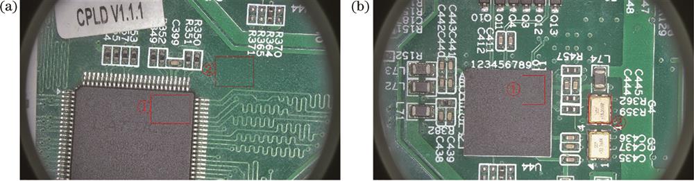
Fig. 2. ROI exposure control diagram.(a) ROI area selection under scene 1, ① relatively low brightness area, ② relatively high brightness area; (b) ROI area selection under scene 2, ① relatively low brightness area, ② relatively high brightness area
Fig. 3. Schematic diagrams of luminance statistics within the ROI. (a) Chunked statistics subregion luminance and weight coefficients; (b) subregion weight distribution
Fig. 4. Schematic diagram of linear variation of convergence step size
Fig. 5. Schematic of the nonlinear variation of the convergence step size
Fig. 6. Exposure control flow diagram
Fig. 7. Schematic diagram of experimental platform
Fig. 8. Comparison of exposure results under scene 1. (a) Original exposure; (b) ROI exposure based on relatively dark areas; (c) ROI exposure based on relatively bright areas
Fig. 9. Comparison of exposure results under scene 2. (a) Original exposure; (b) ROI exposure based on relatively dark areas. (c) ROI exposure based on relatively bright areas
Fig. 10. Schematic diagrams of the exposure convergence process. (a) Initial exposure state; (b) exposure adjustment for the first frame; (c) second frame; (d) third frame exposure convergence
| ||||||||||||||
Table 1. Exposure results under different automatic exposure control methods
| ||||||||||||||
Table 2. Exposure convergence time under different automatic exposure control methods


Set citation alerts for the article
Please enter your email address

© Copyright 2018-2021 | Chinese Laser Press. All Rights Reserved 沪ICP备15018463号-20