• Chinese Optics Letters
  • Vol. 21, Issue 11, 113602 (2023)
Jingcheng Zhao1, Nan Li1,2, and Yongzhi Cheng3,4,*
Author Affiliations
  • 1School of Electronics Information Engineering, Beihang University, Beijing 100191, China
  • 2Aerospace Institute of Advanced Material & Processing Technology, Beijing 100074, China
  • 3School of Information Science and Engineering, Wuhan University of Science and Technology, Wuhan 430081, China
  • 4Hubei Longzhong Laboratory, Xiangyang 441000, China
  • show less
    DOI: 10.3788/COL202321.113602 Cite this Article Set citation alerts
    Jingcheng Zhao, Nan Li, Yongzhi Cheng, "Ultrabroadband chiral metasurface for linear polarization conversion and asymmetric transmission based on enhanced interference theory," Chin. Opt. Lett. 21, 113602 (2023) Copy Citation Text show less
    (a) Schematic diagram of CMS array with the wave propagation, (b) the front (I), middle (II), and back (III) layers of the unit-cell structure.
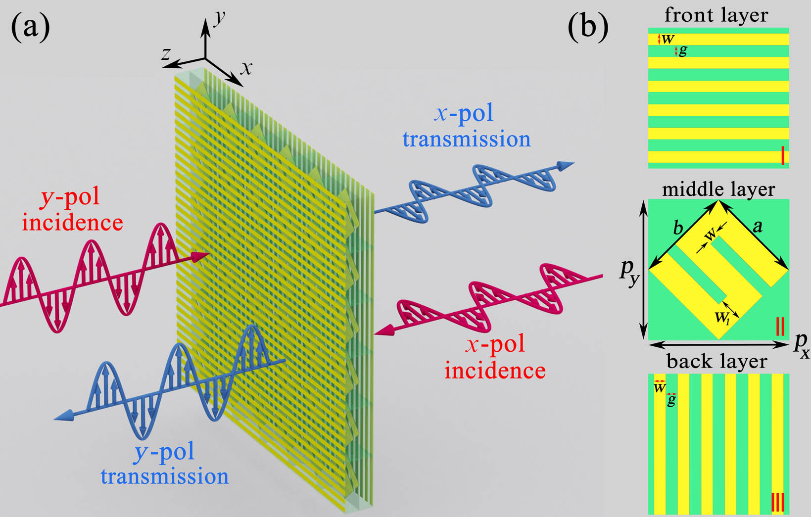
    Fig. 1. (a) Schematic diagram of CMS array with the wave propagation, (b) the front (I), middle (II), and back (III) layers of the unit-cell structure.
    Enhanced LP conversion mechanism of the Fabry–Perot interference model in tri-layered (I, II, III) structure of the proposed CMS.
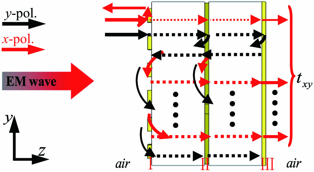
    Fig. 2. Enhanced LP conversion mechanism of the Fabry–Perot interference model in tri-layered (I, II, III) structure of the proposed CMS.
    Fabricated sample of the designed CMS structure. (a), (c) Front layer and (b), (d) middle layer.
    Fig. 3. Fabricated sample of the designed CMS structure. (a), (c) Front layer and (b), (d) middle layer.
    (a) Simulated, (b) measured, and (c) calculated transmission coefficients (txx, txy, tyx and tyy) for the normally incident waves passing through the CMS along (a)–(c) forward (−z) direction (d)–(f) backward (+z) direction.
    Fig. 4. (a) Simulated, (b) measured, and (c) calculated transmission coefficients (txx, txy, tyx and tyy) for the normally incident waves passing through the CMS along (a)–(c) forward (−z) direction (d)–(f) backward (+z) direction.
    (a) Simulated, (b) calculated, and (c) measured PCR (PCRx and PCRy) for x-pol. and y-pol. waves propagating along the forward (−z) direction through the CMS.
    Fig. 5. (a) Simulated, (b) calculated, and (c) measured PCR (PCRx and PCRy) for x-pol. and y-pol. waves propagating along the forward (−z) direction through the CMS.
    The simulated polarization azimuth rotation angle (θ) and polarization ellipticity angle (η) were obtained for the normal incidence of y-pol. waves propagating along the forward (−z) direction through the designed CMS.
    Fig. 6. The simulated polarization azimuth rotation angle (θ) and polarization ellipticity angle (η) were obtained for the normal incidence of y-pol. waves propagating along the forward (−z) direction through the designed CMS.
    (a) Simulated, (b) calculated, and (c) measured total transmittance (Tx) for x-pol. and y-pol. waves propagating along the forward (−z) and backward (+z) directions through the CMS.
    Fig. 7. (a) Simulated, (b) calculated, and (c) measured total transmittance (Tx) for x-pol. and y-pol. waves propagating along the forward (−z) and backward (+z) directions through the CMS.
    (a) Simulated, (b) calculated, and (c) measured AT coefficients (Δlin) for the normally incident x-pol. and y-pol. waves propagating through the designed CMS.
    Fig. 8. (a) Simulated, (b) calculated, and (c) measured AT coefficients (Δlin) for the normally incident x-pol. and y-pol. waves propagating through the designed CMS.
    Simulated electric field vector distributions in the y–z plane for the CMS unit-cell structure under the normally incident (a)–(c) y-pol. and (d)–(f) x-pol. waves propagating along the forward (−z) direction at different resonance frequencies. (a), (d) f1 = 4.32 GHz; (b), (e) f2 = 7.94 GHz; (c), (f) f3 = 14.96 GHz.
    Fig. 9. Simulated electric field vector distributions in the y–z plane for the CMS unit-cell structure under the normally incident (a)–(c) y-pol. and (d)–(f) x-pol. waves propagating along the forward (−z) direction at different resonance frequencies. (a), (d) f1 = 4.32 GHz; (b), (e) f2 = 7.94 GHz; (c), (f) f3 = 14.96 GHz.
    ReferencesFrequency Range (GHz)Bandwidth of PCR (≥ 0.95) (%)Bandwidth of AT (≥ 0.5) (%)Thickness (mm)
    [19]8.58–9.7312.5611.50.786
    [28]4.36–14.91104.49103.65.1
    [33]9.8–10.56.95.10.8
    [36]19.4–22.715.611.040.8
    [37]6.8–11.954.553.63.0
    This work3.7–18131.79121.55.1
    Table 1. Performance Comparison of the Proposed CMS with Previous Works
    Jingcheng Zhao, Nan Li, Yongzhi Cheng, "Ultrabroadband chiral metasurface for linear polarization conversion and asymmetric transmission based on enhanced interference theory," Chin. Opt. Lett. 21, 113602 (2023)
    Download Citation