• Laser & Optoelectronics Progress
  • Vol. 62, Issue 3, 0312001 (2025)
Baoli Guo*, Jiarui Lin, Mingxin Teng, Rao Zhang, and Jigui Zhu
Author Affiliations
  • State Key Laboratory of Precision Measurement Technology and Instruments, Tianjin University, Tianjin 300072, China
  • show less
    DOI: 10.3788/LOP241116 Cite this Article Set citation alerts
    Baoli Guo, Jiarui Lin, Mingxin Teng, Rao Zhang, Jigui Zhu. Evaluation Method for Structural Strength of Directional Network of Workshop Measurement and Positioning System[J]. Laser & Optoelectronics Progress, 2025, 62(3): 0312001 Copy Citation Text show less
    Schematic diagram of wMPS transmitter structure and mathematical model of single-station measurements. (a) Schematic diagram of the wMPS transmitter structure; (b) mathematical model of single-station measurements
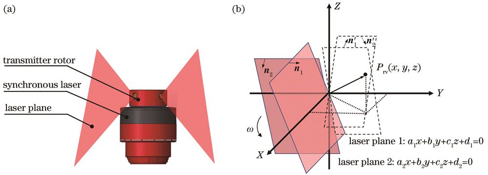
    Fig. 1. Schematic diagram of wMPS transmitter structure and mathematical model of single-station measurements. (a) Schematic diagram of the wMPS transmitter structure; (b) mathematical model of single-station measurements
    Schematic diagram of wMPS multi-station measurements
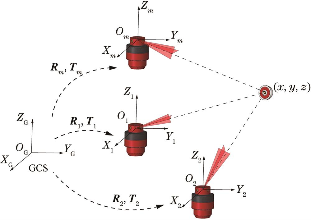
    Fig. 2. Schematic diagram of wMPS multi-station measurements
    Schematic diagram of wMPS directional network
    Fig. 3. Schematic diagram of wMPS directional network
    Flowchart of simulating and solving DNSC
    Fig. 4. Flowchart of simulating and solving DNSC
    Geometric layout of four directional constraint points. (a)(d) Circular layout; (b)(e) semi-circular layout; (c)(f) scalloped layout
    Fig. 5. Geometric layout of four directional constraint points. (a)(d) Circular layout; (b)(e) semi-circular layout; (c)(f) scalloped layout
    Effect of change in distance from the constraint point to transmitting station on DNSC. (a) DNSC of layout a; (b) DNSC of layout b; (c) DNSC of layout c
    Fig. 6. Effect of change in distance from the constraint point to transmitting station on DNSC. (a) DNSC of layout a; (b) DNSC of layout b; (c) DNSC of layout c
    Impact of number of constraint points on DNSC. (a) DNSC of layout a; (b) DNSC of layout b; (c) DNSC of layout c
    Fig. 7. Impact of number of constraint points on DNSC. (a) DNSC of layout a; (b) DNSC of layout b; (c) DNSC of layout c
    Change of DNSC when transmitting station moves along X-axis. (a) DNSC of layout a; (b) DNSC of layout b; (c) DNSC of layout c
    Fig. 8. Change of DNSC when transmitting station moves along X-axis. (a) DNSC of layout a; (b) DNSC of layout b; (c) DNSC of layout c
    Change of DNSC when transmitting station moves along Y-axis. (a) DNSC of layout a; (b) DNSC of layout b; (c) DNSC of layout c
    Fig. 9. Change of DNSC when transmitting station moves along Y-axis. (a) DNSC of layout a; (b) DNSC of layout b; (c) DNSC of layout c
    Experimental scene and schematic diagram. (a) Experimental scenes; (b) schematic diagram of scene
    Fig. 10. Experimental scene and schematic diagram. (a) Experimental scenes; (b) schematic diagram of scene
    Relative error of uncertainty of pose parameter
    Fig. 11. Relative error of uncertainty of pose parameter
    Distance of test point to laser planes under different directional networks. (a) Distance from test point to laser plane 1; (b) distance from test point to laser plane 2
    Fig. 12. Distance of test point to laser planes under different directional networks. (a) Distance from test point to laser plane 1; (b) distance from test point to laser plane 2
    σ0 /″Gα /%Gβ /%GY /%Gtx /%Gty /%Gtz /%
    198.0099.3398.3399.00100.0097.33
    298.33100.0097.6798.0098.3398.00
    398.3397.33100.0097.3398.0098.00
    497.3399.0097.6799.33100.0099.00
    599.6797.3397.3398.6798.0098.00
    697.6798.6797.3398.6797.3399.33
    Table 1. Verification results of pose parameter uncertainty based on different scan angle uncertainties
    Points numberGα/%Gβ/%GY/%Gtx/%Gty/%Gtz/%
    699.798.398.798.798.399.7
    1299.398.399.799.3100.0100.0
    1899.799.399.3100.098.098.3
    2498.3100.098.399.799.398.7
    30100.098.399.099.098.799.7
    3699.098.3100.099.398.398.7
    4299.399.0100.098.099.3100.0
    4899.3100.099.0100.0100.099.3
    Table 2. Verification results of pose parameter uncertainty based on different constraint points number
    LayoutDNSC,αDNSC,βDNSC,γDNSC,tx /(μm·arcsec-1DNSC,ty /(μm·arcsec-1DNSC,tz /(μm·arcsec-1
    a0.300.300.217.07.05.0
    b0.470.360.2911.77.36.9
    c3.430.553.2686.313.275.3
    d0.300.300.2114.114.110.0
    e0.470360.2923.414.513.8
    f3.430.553.26172.526.5150.6
    Table 3. DNSC for different constraint point layouts
    Directional networkDNSC,αDNSC,βDNSC,γDNSC,tx /(μm·arcsec-1DNSC,ty /(μm·arcsec-1DNSC,tz /(μm·arcsec-1
    11.291.381.8647.635.253.7
    21.932.833.11109.861.2111.2
    32.643.133.25125.1120.6162.4
    Table 4. DNSC for different directional networks
    Laser planeDN 1 /mmDN 2 /mmDN 3 /mm
    10.0390.0760.099
    20.0510.0770.117
    Table 5. Average distance from test point to laser plane based on different directional networks
    Baoli Guo, Jiarui Lin, Mingxin Teng, Rao Zhang, Jigui Zhu. Evaluation Method for Structural Strength of Directional Network of Workshop Measurement and Positioning System[J]. Laser & Optoelectronics Progress, 2025, 62(3): 0312001
    Download Citation