
Xiu-Min YAO, Xiao-Jie WANG, Xue-Jian LIU, Zhong-Ming CHEN, Zheng-Ren HUANG. Friction-wear Properties and Mechanism of Hard Facing Pairs of SiC and WC [J]. Journal of Inorganic Materials, 2019, 34(6): 673
- Journal of Inorganic Materials
- Vol. 34, Issue 6, 673 (2019)
Abstract
Silicon carbide (SiC) has been used as abrasive and seal materials, due to its unique properties, such as low density, high strength, high thermal conductivity, high hardness, high elastic modulus, excellent thermal shock resistance and superior chemical inertness. In order to ensure the safety of the engineering use, the friction- wear properties of SiC ceramics must be investigated. Microstructure engineering has been proved to be an effective strategy to improve the silding-wear resistance of polycrystalline structure ceramics[
In recent years, pressurelessly sintered silicon carbide (PLS SiC) ceramics developed as a new kind of seal materials due to its high strength, good oxidation resistance and excellent chemical resistance. It can be submerged in the corrosive environments, subjected to extreme wear and abrasive conditions, and exposed to the temperatures exceeding 1400 ℃. There are two kinds of PLS SiC ceramics, one is solid-state-sintered SiC ceramics (SSiC), which are usually prepared by adding B-C as sintering aids, the other is liquid-phase-sintered SiC ceramics (LPSiC), which are usually fabricated by adding Al2O3-Y2O3 as sintering aids[
Sang, et al[
In recent years, in some harsh operation conditions, especially high rotation speed and high temperature system, the mechanical seal tends to be hard-face to hard-face seal due to their excellent wear resistance and long service life, such as, SiC/WC pairs. Until now, there are few research reports on the sealing properties and friction properties of those pairs.
In this work, we focused on the friction-wear properties of SiC/WC pairs. The properties and microstructure of the materials were analyzed. The friction-wear properties, friction surface and friction mechanism of them were also discussed.
1 Experimental procedure
1.1 Samples preparations
SSiC ceramics were prepared with 96.4wt% α-SiC powders (D50=0.5 μm, SIKA TECH., Lillesand, Norway), 3.0wt% carbon black and 0.6wt% boron carbide particles as raw materials. The raw materials were ball milled with ethanol as media, dried at 60 ℃. After being meshed, the powders were died pressed at 40 MPa, cold isostaticly pressed at 200 MPa to fabricate green samples, then the as-prepared specimens were sintered at 2150 ℃ for 1 h to obtain the ceramics.
LPSiC ceramics were prepared with 93wt% α-SiC powders, 3.12wt% Al2O3 pwders (Fenghe Ceramic Co., Ltd., China) and 3.88wt% Y2O3 powders (Yuelong Chemical Co., Ltd., China) as raw materials. The procedure to fabricate LPSiC ceramics was the same with that of SSiC ceramics except that they were finally sintered at 1930 ℃ for 1 h.
The WC materials (N200, 8wt%~9wt% Ni-0.8~1.2wt% (Cr+Mo)-89.8wt%~91.2wt% WC) were provided by KLT Carbide Co. Ltd., Sichuan, China, which were fabricated by gas pressure sintering method.
The as-sintered samples were machined into rectangular blocks with a dimension of 6 mm×7 mm×30 mm and rings with a dimension of internal diameter ϕ16 mm and external diameter ϕ40 mm. And the thickness of the rings was 10 mm. The surfaces of the bars were polished using polishing machinery with diamond slurries.
1.2 Test and characterization
The bulk densities of the samples were measured by Archimedes method using distilled water as immersing medium. The Vickers’ hardness (Hv) of the samples was measured on the polished surfaces by Vickers indentation (Wilson-Wolpert Tukon 2100B, Canton, MA) using a load of 3 kg. Rockwell hardness (HRA) of the samples was tested on the polished surfaces by Rockwell indentation (Wilson-2000, Canton, MA) using a load of 60 kg. Fracture toughness (KIC) of the samples was calculated by the Vickers indentation method on the basis of the equation proposed by Niihara, et al[
The friction test was performed on a ring-block friction testing machine (MM200, Jinan test machine factory, China). During the friction, the ring was rotated and the block was fixed. In the present study, four groups of samples were tested without lubrication (dry friction) or with water as lubrication in every pairs (ΦWC/SSiC, ΦWC/LPSiC, ΦSSiC/WC, ΦLPSiC/WC). The rotation speed and load were 400 r/min (0.82 m/s) and 196 N, respectively. Three pairs of samples were tested in every friction condition. The specimens were cleaned before and after the tests by immersing in acetone with agitation in an ultrasonic bath for 20 min to calculate the weight loss during the friction process.
2 Results and discussion
Table 1 shows the properties of the used materials. It can be clearly seen that the relative density of these three kinds of materials are over 99%, which means that the samples are highly densified and have few visible pores (seen in Fig. 1). By comparison, the SSiC ceramics have the lowest fracture toughness and highest hardness, the WC materials have the highest fracture toughness and lowest hardness, and the fracture toughness and hardness of LPSiC ceamics are in the median.
| Composite/wt% | Grain size/μm | Relative density/% | Fracture toughness/(MPa·m1/2) | HV3.0/GPa | HRA | |
|---|---|---|---|---|---|---|
| SSiC | 96.4SiC-3.0C-0.6B4C | 3-5 | >99 | (2.96±0.20) | (20.78±0.96) | (93.4±0.1) |
| LPSiC | 93SiC-7YAG | <2 | >99 | (3.66±0.23) | (19.72±0.52) | (92.7±0.3) |
| WC | 89.9~91.2WC-8~9Ni- | <3 | >99 | (6.65±0.29) | (14.86±0.46) | (90.4±0.1) |
Table 1.
Properties of the prepared materials
![]()
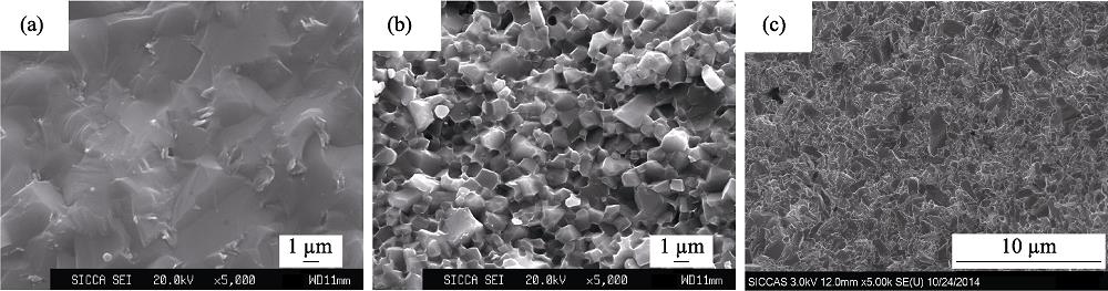
Figure .Fracture microstructures of three kinds of samples
Figure 1 shows the fracture surface microstructures of these three kinds of samples. It can be seen that the fracture mode of SSiC cermics is complete transgranular fracture, showing the strong interface bonding between the SiC grains. Compared with the other two kinds of materials, SSiC ceramics were obtained at higher temperature via a solid-state sintering route, so SSiC ceramics had bigger grain sizes of about 3-5 μm. Both of them led to the higher hardness and lower fracture toughness of SSiC ceramics. It can be also seen that the fracture mode of LPSiC ceramics is mainly intergranular fracture because of the interface YAG phases between SiC grains, which were formed during the liquid-phase-sintering process and led to the weak interface bonding between the SiC grains. And the SiC particle sizes in LPSiC ceramics are about 1-2 μm due to their lower sintering temperature. Interface phase, intergranular fracture mode and smaller particle sizes led to the lower hardness and higher fracture toughness of LPSiC ceramics. In the WC samples, the grain sizes of WC particles are smaller than 3 μm, the highest fracture toughness and lowest hardness of the samples were obtained due to their metal features.
Table 2 and 3 show the friction properties of different SiC/WC pairs. Under dry friction condition, all friction pairs have higher friction coefficient (μ). However, compared with the pairs containing SSiC ceramics, the pairs containing LPSiC ceramics have lower friction coefficient and higher friction mass loss. It is well documented that coarser ceramics have poorer sliding- wear property[
| Materials of ring/block | Friction coefficient | (Δm/m) of block/% | (Δm/m) of ring/% |
|---|---|---|---|
| ΦSSiC/WC | (0.70±0.02) | (-0.0029±0.0001) | 0 |
| ΦWC/SSiC | (0.66±0.09) | (-0.0009±0.0004) | (-0.0036±0.0023) |
| ΦLPSiC/WC | (0.63±0.01) | (-0.0041±0.0005) | (-0.0038±0.0009) |
| ΦWC/LPSiC | (0.57±0.01) | (-0.0034±0.0008) | (-0.0105±0.0019) |
Table 2.
Friction properties of different pairs of SiC/WC under dry friction
From Table 3, it can be seen that, with water as lubrication, the μ of all pairs are lower than 0.1 and the mass loss can be negligible. Meanwhile, the μ of LPSiC/WC pairs is higher than that of SSiC/WC pairs, which is contrary to that of dry friction.
| Materials of ring/block | Friction coefficient | (Δm/m) of block/% | (Δm/m) of ring/% |
|---|---|---|---|
| ΦSSiC/WC | (0.031±0.001) | (-0.0004±0.0001) | (-0.0010±0.0001) |
| ΦWC/SSiC | (0.018±0.004) | (-0.0004±0.0001) | (+0.0004±0.0004) |
| ΦLPSiC/WC | (0.093±0.004) | (-0.0002±0.0001) | (-0.0008±0.0001) |
| ΦWC/LPSiC | (0.020±0.007) | (-0.0004±0.0001) | (-0.0003±0.0006) |
Table 3.
Friction properties of different pairs of SiC/WC with water as lubrication
From Table 2 and 3, in SiC/WC pairs, when SiC ceramics (both SSiC and LPSiC ceramics) were as fixed friction materials (as blocks), the μ of the pairs is lower than that with WC materials as fixed friction materials. Under fry friction, the wear rate of the former is higher than that of the latter. Therefore, in order to decrease μ, it is a good option to choose the SiC ceramics as the fixed friction materials; in order to decrease the wear, it would be better to choose WC materials as the fixed friction materials in the SiC/WC friction pairs.
Figure 2 shows the wear face microstructure of the blocks in different WC/SiC pairs under dry friction. Comparing with SiC ceramics as the fixed blocks, the friction marks of WC materials as the fixed blocks are fewer, and there are no obvious SiC materials on the surfaces of WC blocks (seen in Fig. 2(a) and (b)). However, there is a lot of debris on the surface of SiC ceramics (seen in Fig. 2(c) and (d)). Both of them show that the wear rate of the pairs with SiC as the fixed friction materials is higher than that of the pairs with WC as the fixed friction materials, which is in agreement with the result in Table 2. It can be also seen that no WC particles are pulled out on the surface of WC materials. Because the friction test is ring-to-block mode, the friction heat was mainly produced in the friction surface and stored in the block, which led to the severe wear of the block. When WC materials were used as blocks, plastic deformation took place continuously in the WC materials due to its high toughness. In the end, cracks were induced by fatigue damage (seen in Fig. 2(b)) and the roughness of WC materials increased, which led to the increase of friction coefficient. With SiC materials as the fixed blocks, a lot of debris were observed on the over worn surfaces, which demonstrated that SiC ceramics or WC materials were worn down.
![]()
Figure .Wear face microstructures of the blocks in different WC/SiC pairs without lubrication
Figure 3 shows the worn face microstructure of SiC samples in different pairs. From Fig. 3(a), cracks are detected in SSiC ceramics after dry friction test, while no cracks are found in the LPSiC ceramics in the detected area. Usually for the same materials, the tendency of crack’s formation is stronger in the samples of fine particles than that of coarse ones, because the peak stress could be limited due to a uniform distribution of the stress for the coarse particles[
![]()
Figure .Wear face microstructures of SiC samples in different pairs
Figure 4 shows the EDS mapping of the worn surface of SSiC blocks in ΦWC/SSiC pairs. Obviously, the Si element matches with C element very well in these areas. It can be also seen that W element matches quite well with O element, which indicated that WO3 was formed in the wear area. The existence of WO3 indicated that oxidative wear occurred in the dry friction. The same phenomena were observed in the ΦWC/LPSiC samples. During the friction process, the SiC particles were broken in SSiC samples and pulled out in LPSiC ceramics under the applied force, which were as the abrasive to wear the samples and produce the debris. From Fig. 3(b), the sizes of WO3 particles were lower than 200 nm. Smaller debris size and a large amount of friction heat led to the oxidation of WC debris into WO3. And the soft WO3 phase is beneficial to reduce the friction efficient.
![]()
Figure .EDS mapping of the worn surface of SSiC blocks in
Figure 5 shows the micro-area XRD pattern of the worn surface of SSiC blocks in ΦWC/SSiC pairs under dry condition. The result showed that the debris consists of SiC as a major phase and graphite as the co-existence phase. No WC, WO3 and SiO2 phases are detected. Both of them indicated that all abrasive WC phases were transferred to WO3 (seen in Fig. 4), which existed as an amorphous phase. At the same time, the peaks of SiC phase were similar to the original SSiC ceramics, which meant few SiC phase existed in the debris. Therefore, the X-ray diffraction pattern of SiC phases were from the original SSiC ceramics. The same phenomenon was observed in ΦWC/LPSiC pairs.
![]()
Figure .Micro-area XRD pattern of the worn surface of SSiC blocks in
3 Conclusions
Friction-wear properties of different SiC/WC pairs were investigated under dry friction conditions or with water as lubrication. Compared to LPSiC/WC pairs, the SSiC/WC pairs have higher friction coefficient and less mass loss because SSiC ceramics have larger particles size and higher hardness. The friction coefficient of the pairs with SiC ceramics as the fixed friction materials is lower than that with WC materials as the fixed friction materials. The wear rate of the former is higher than that of the latter due to the lower hardness of WC. The WC debris was oxidized to amorphous WO3 phase due to friction heat and the smaller debris sizes.


Set citation alerts for the article
Please enter your email address

© Copyright 2018-2021 | Chinese Laser Press. All Rights Reserved 沪ICP备15018463号-20