Author Affiliations
1Tianjin Key Laboratory of Integrated Design and On-line Monitoring for Light Industry & Food Machinery and Equipment, College of Mechanical Engineering, Tianjin University of Science & Technology, Tianjin 300222, China2Yipu Optoelectronics (Tianjin) Co., Ltd., Tianjin 300385, Chinashow less
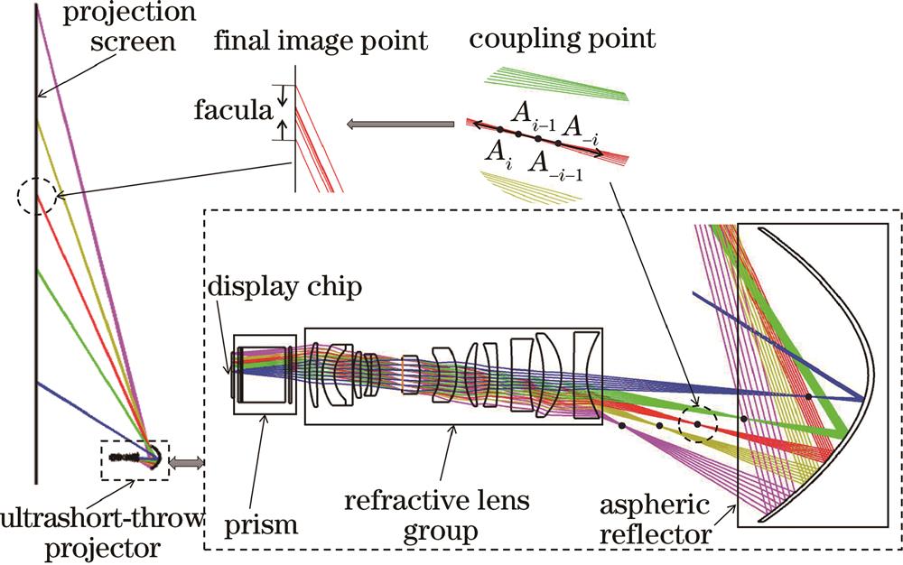
Fig. 1. Schematic of catadioptric ultrashort-throw projection optical system
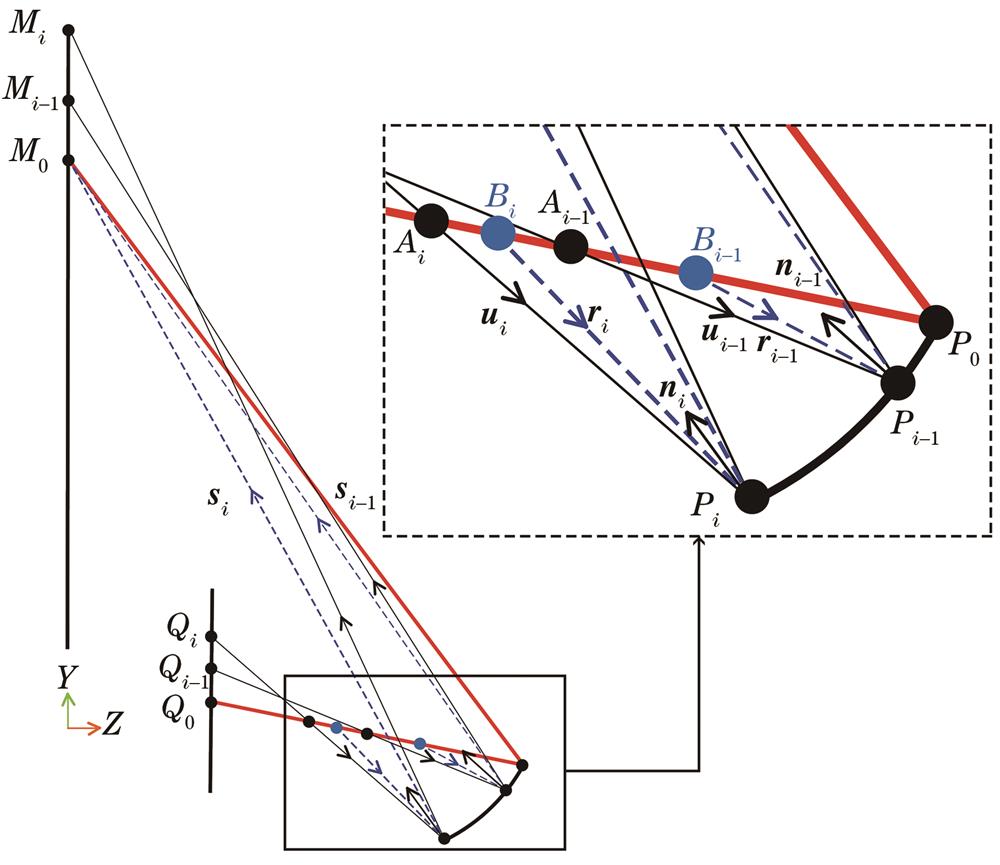
Fig. 2. Schematic of coupling point error calculation
Fig. 3. Process of building the initial structure
Fig. 4. Variation of coupling deviation of each field-of-view before and after controlling coupling deviation
Fig. 5. Variation of spot radius of each field-of-view before and after controlling coupling deviation
Fig. 6. Spot radius of the initial structure and the forward final optical system
Fig. 7. Relative distortion of the initial structure
Fig. 8. Flow chart of overall optimization
Fig. 9. Comparison of coupling deviation. (a) Initial structural coupling deviation; (b) positive final coupling deviation
Fig. 10. Final optical system structure
Fig. 11. Spot radius of reverse final optical system
Fig. 12. Distortion of the reverse final optical system. (a) Relative distortion; (b) grid distortion
Fig. 13. MTF curve of the reverse final optical system
Parameter | Value |
---|
Display chip size | 0.37 inch,1920×1080 | Screen size | 100 inch(2540 mm) | F-number | 2.6 | Projection ratio | 0.22 | Image offset | 140% | Telecentric degree | <1° | TV distortion | horizontal<0.5%;vertical<0.4% | MTF | >0.5@117 lp/mm |
|
Table 1. Technical parameters of ultrashort-throw projection optical system
Surfuce | Type | Radius /mm | Thickness /mm | Material | Surfuce | Type | Radius /mm | Thickness /mm | Material |
---|
S0 | Standard | Infinity | 486.860 | — | S14 | Standard | -20.269 | -1.100 | H-LAK54 | S1 | Odd asphere | -145.132 | -74.652 | MIRROR | S15 | Standard | -9.066 | -2.671 | D-LAK5 | S2 | Even asphere | 17.724 | -3.500 | F52R | S16 | Standard | 33.592 | -0.116 | — | S3 | Even asphere | 66.033 | -0.117 | — | STOP | Standard | Infinity | -0.116 | — | S4 | Standard | -19.409 | -5.487 | H-ZF52 | S18 | Standard | -112.211 | -2.402 | H-FK71 | S5 | Standard | -51.029 | -3.896 | — | S19 | Standard | 11.524 | -1.100 | TAFD55 | S6 | Standard | 46.507 | -5.139 | FDS1 | S20 | Standard | -29.148 | -5.441 | — | S7 | Standard | -72.032 | -2.939 | — | S21 | Even asphere | 160.592 | -3.468 | D-K9 | S8 | Standard | 42.570 | -2.155 | D-LAF50 | S22 | Even asphere | 11.473 | -0.144 | — | S9 | Standard | -125.874 | -5.329 | — | S23 | Standard | 40.344 | -3.822 | H-FK61 | S10 | Standard | 29.217 | -4.294 | F3 | S24 | Standard | 11.392 | -3.334 | TAFD55 | S11 | Standard | 17.373 | -11.000 | — | S25 | Standard | 15.662 | -0.145 | — | S12 | Standard | -32.682 | -4.099 | ZF13 | S26 | Standard | 110.797 | -1.997 | H-ZF88 | S13 | Standard | -445.750 | -10.938 | — | S27 | Standard | 34.345 | -5.000 | — |
|
Table 2. Structural parameters of optical system
Order | Conic | 2th order term | 3th order term | 4th order term |
---|
Aspheric coefficient | 5.986 | -0.015 | -2.171×10⁻⁴ | 2.482×10⁻⁵ | Order | 5th order term | 6th order term | 7th order term | 8th order term | Aspheric coefficient | -8.655×10⁻⁷ | 1.536×10⁻⁸ | -1.377×10⁻¹⁰ | 4.469×10⁻¹³ |
|
Table 3. Aspheric coefficient of reflector
Order | S2 | S3 | S21 | S22 |
---|
Conic | 0.034 | 9.727 | 0 | 0 | 4th order term | -1.584×10⁻⁴ | -1.239×10⁻⁴ | 7.708×10⁻⁵ | -2.909×10⁻⁵ | 6th order term | 1.896×10⁻⁶ | 1.869×10⁻⁶ | 7.018×10⁻⁷ | 3.206×10⁻⁷ | 8th order term | -1.942×10⁻⁸ | -2.136×10⁻⁸ | -2.645×10⁻⁸ | -2.236×10⁻⁹ | 10th order term | 1.208×10⁻¹⁰ | 1.565×10⁻¹⁰ | 1.222×10⁻¹⁰ | -1.283×10⁻¹⁰ | 12th order term | -4.768×10⁻¹³ | -7.472×10⁻¹³ | 0 | 0 | 14th order term | 1.077×10⁻¹⁵ | 2.074×10⁻¹⁵ | 0 | 0 | 16th order term | -1.077×10⁻¹⁸ | -2.545×10⁻¹⁸ | 0 | 0 |
|
Table 4. Coefficient of even aspheric surface