• Laser & Optoelectronics Progress
  • Vol. 55, Issue 3, 032302 (2018)
Le Lian*, Jie Fu, Chaoshan Yang, and Genliang Han
Author Affiliations
  • School of Electronic and Information Engineering, Lanzhou Jiaotong University, Lanzhou, Gansu 730070, China
  • show less
    DOI: 10.3788/LOP55.032302 Cite this Article Set citation alerts
    Le Lian, Jie Fu, Chaoshan Yang, Genliang Han. Research and Application of Output Spectrum of Parallel Five-Microring Resonator Frequency Band[J]. Laser & Optoelectronics Progress, 2018, 55(3): 032302 Copy Citation Text show less
    Schematic of parallel microring array
    Fig. 1. Schematic of parallel microring array
    Diagram of transmission unit model
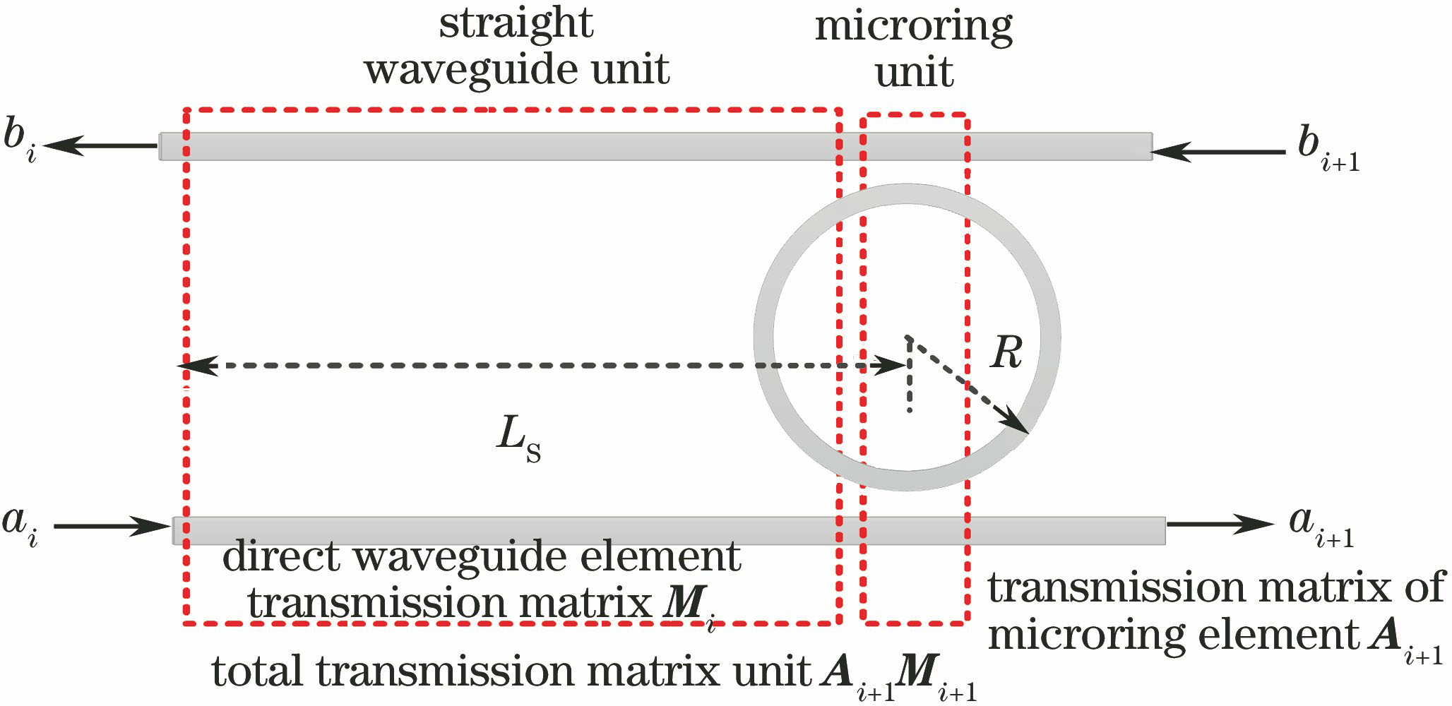
    Fig. 2. Diagram of transmission unit model
    Schematic of parallel five-microring array
    Fig. 3. Schematic of parallel five-microring array
    Downloaded frequency spectra with different transmission coupling coefficients (LS=0.5πR)
    Fig. 4. Downloaded frequency spectra with different transmission coupling coefficients (LS=0.5πR)
    Downloaded frequency spectra with different transmission coupling coefficients (LS=πR)
    Fig. 5. Downloaded frequency spectra with different transmission coupling coefficients (LS=πR)
    Spectrogram of the optimized resonator frequency band
    Fig. 6. Spectrogram of the optimized resonator frequency band
    Frequency bands of resonator with different system refractive indexes
    Fig. 7. Frequency bands of resonator with different system refractive indexes
    Frequency bands of resonator with different microring radii
    Fig. 8. Frequency bands of resonator with different microring radii
    Influence of (a) loss coefficient of microring and (b) fractionated gain on frequency band of resonator
    Fig. 9. Influence of (a) loss coefficient of microring and (b) fractionated gain on frequency band of resonator
    Diagram of wavelength demultiplexing
    Fig. 10. Diagram of wavelength demultiplexing
    Schematic of 1×4 DWDM
    Fig. 11. Schematic of 1×4 DWDM
    Frequency spectra of DWDM channel output
    Fig. 12. Frequency spectra of DWDM channel output
    Microringradius /μmLoss coefficient ofmicroring /(dB·cm-1)Tapewidth /GHzInsertionloss /dBStopbandcrosstalk /dBForm factor
    400.526.25-0.5-26.50.86
    401.525.00-1.6-27.00.83
    Table 1. Simulation parameter comparison
    ChannelFWHM /nmTape width /GHzForm factorInsertion loss /dBStopband crosstalk /dB
    C10.2025.00.85-0.50-28.4
    C20.1923.80.86-0.80-27.6
    C30.1923.80.86-0.85-27.4
    C40.1923.80.86-0.90-27.3
    Table 2. Parameters of different DWDM channels
    Le Lian, Jie Fu, Chaoshan Yang, Genliang Han. Research and Application of Output Spectrum of Parallel Five-Microring Resonator Frequency Band[J]. Laser & Optoelectronics Progress, 2018, 55(3): 032302
    Download Citation