
Tong Ma, Hong-Xian Xie. Formation mechanism of face-centered cubic phase in impact process of single crystal iron along [101] direction [J]. Acta Physica Sinica, 2020, 69(13): 130202-1
- Acta Physica Sinica
- Vol. 69, Issue 13, 130202-1 (2020)
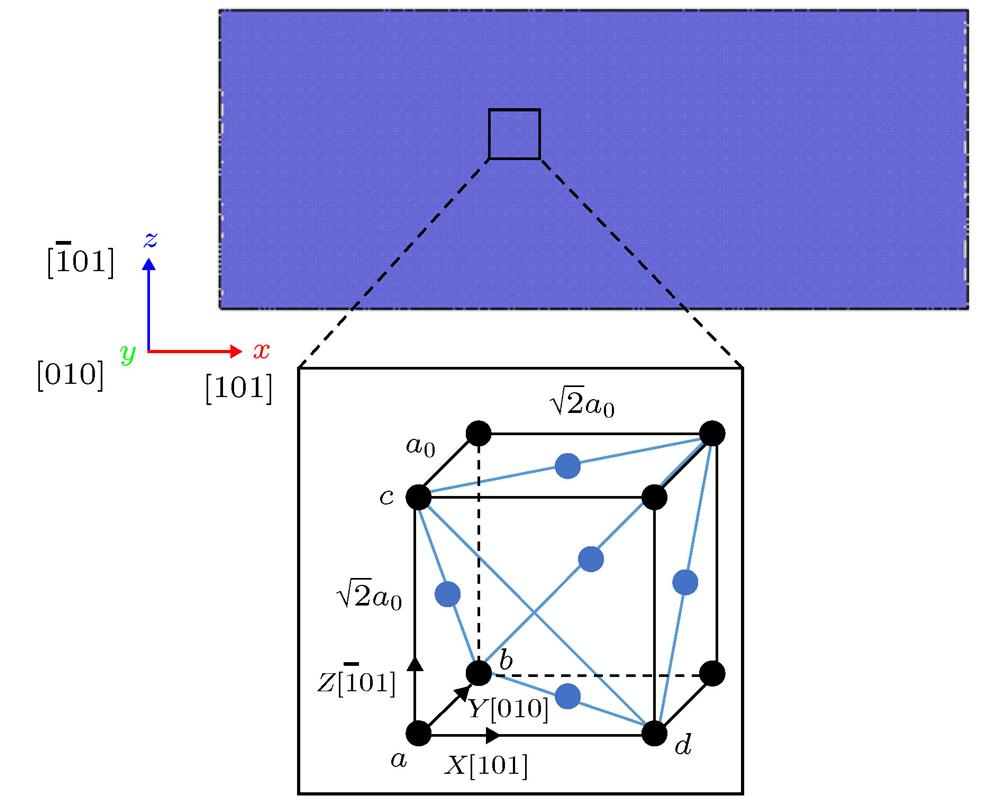
Fig. 1. Initial model of BCC iron impact.
![The simulation of a single crystal iron model which was impacted along [101] crystal direction (the impact speed was 1.05 km/s): (a) The stress in the impacted sample at different times; (b) the impacted sample at 8 ps. Blue and red parts represent BCC and HCP phase, respectively; green part represents FCC or stacking fault of HCP phase.](/richHtml/wlxb/2020/69/13/20191877/img_2.jpg)
Fig. 2. The simulation of a single crystal iron model which was impacted along [101] crystal direction (the impact speed was 1.05 km/s): (a) The stress in the impacted sample at different times; (b) the impacted sample at 8 ps. Blue and red parts represent BCC and HCP phase, respectively; green part represents FCC or stacking fault of HCP phase.
Fig. 3. The atoms’ configuration on the (101) plane after impaction (blue, red and green balls represent the iron atoms in BCC phase, HCP phase and FCC phase (or stacking fault of HCP), respectively.
Fig. 4. The formation mechanisms of HCP and FCC phase under impact of BCC iron along [101] direction: (a) The BCC-HCP phase transition mechanism of a structural unit; (b) the atomic motion of (101) plane (yellow arrow represents the contraction direction of (101) plane, and black arrow represents the relative sliding direction of (101) plane (atoms 1—6 and 7—9 correspond to the first and second atomic planes in (a) respectively; u is the relative sliding distance of (101) plane); (c) the change of atomic distance with impact time; (d) BCC-FCC phase transition mechanism (set the face center atom in the structural unit to yellow for easy observation); (e) the change of lattice constant with impact time.
Fig. 5. The transformation mechanism of BCC iron under uniaxial compression along [101] direction: (a) Three snapshots during compression (b) the variation of stress, lattice constant and energy of single atom (
 ) with loading time; (c) the phase transition process of a structural unit (set the face center atom in the structural unit to yellow for easy observation).
) with loading time; (c) the phase transition process of a structural unit (set the face center atom in the structural unit to yellow for easy observation). Fig. 6. The phase transformation mechanism of BCC iron under simultaneous compression along [101] and
 directions: (a) Three snapshots during compression; (b) the variation of stress, lattice constant and energy of single atom with loading time; (c) the phase transition process of a structural unit (set the face center atom in the structural unit to yellow for easy observation).
directions: (a) Three snapshots during compression; (b) the variation of stress, lattice constant and energy of single atom with loading time; (c) the phase transition process of a structural unit (set the face center atom in the structural unit to yellow for easy observation). Fig. 7. The transformation mechanism of BCC iron under simultaneous compression along [101] and [010] directions: (a) Three snapshots during compression (blue and red spheres represent the iron atoms of BCC and HCP phases respectively); (b) the variation of stress, atomic distance and energy of single atom with loading time (the atomic distance corresponds to the atom in (c)); (c) BCC-HCP phase transformation process (yellow arrow represents the contraction direction of (101) plane, and black arrow represents the relative sliding direction of (101) plane).
Fig. 8. The phase transformation mechanism of BCC iron under triaxial compression: (a) Three snapshots during compression (blue and red spheres represent the iron atoms of BCC and HCP phases respectively); (b) the variation of stress, atomic distance and energy of single atom with loading time (the atomic distance corresponds to the atom in (c)); (c) BCC-HCP phase transformation process ( yellow arrow indicates the contraction direction of (101) plane atom, and black arrow indicates the relative sliding direction of (101) plane atom).
Fig. 9. Gibbs free energies of BCC, HCP and FCC phases change with pressure.


Set citation alerts for the article
Please enter your email address

© Copyright 2018-2021 | Chinese Laser Press. All Rights Reserved 沪ICP备15018463号-20