
Xiaoli Liu, Yang Yang, Jing Yu, Yupei Miao, Xiaojie Zhang, Xiang Peng, Qifeng Yu. Progresses on Imaging System Calibration and 3D Measurement Based on Ray Model[J]. Laser & Optoelectronics Progress, 2022, 59(14): 1415001
- Laser & Optoelectronics Progress
- Vol. 59, Issue 14, 1415001 (2022)
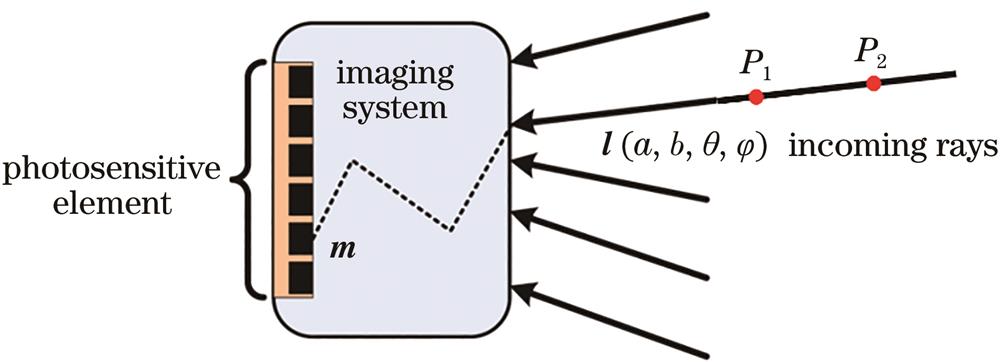
Fig. 1. Schematic of ray model of imaging system
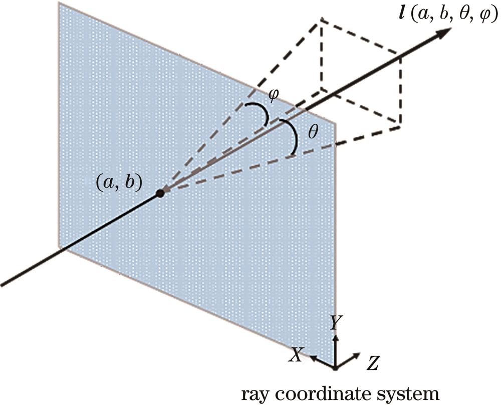
Fig. 2. Schematic of ray's parameter representation
Fig. 3. Calibration of three-point ray model
Fig. 4. Biplane calibration method[43]. (a) Target pose planning with biplane method; (b) binary encoded image; (c) index table
Fig. 5. Calibration of universal ray model[44]. (a) Pinhole camera; (b) fish eye lens
Fig. 6. Ray calibration scheme for large field-of-view imaging system[45]. (a) Pose planning of target for large field-of-view fish eye lens; (b) pose planning of target for spherical catadioptric system; (c) pose planning of target for ray calibration of non-central fish eye camera
Fig. 7. Calibration of multi-view imaging system[46]. (a) Binocular stereo system; (b) catadioptric system composed of spherical mirror and perspective camera
Fig. 8. Ray implicit calibration method[54]
Fig. 9. Residual vector maps after distortion correction[58]. (a) Checkerboard method; (b) active target method
Fig. 10. Scheimpflug structure of fringe structured light microscopic three-dimensional measurement system[61]
Fig. 11. Principle of fringe structured light three-dimensional measurement based on ray model[61]
Fig. 12. Diagram of simplified target attitude[61]
Fig. 13. Small field-of-view fringe projection measurement system based on Scheimpflug structure[62]
Fig. 14. Local three-dimensional measurement results of a nickel coin[61]
Fig. 15. Diagram of light field imaging device. (a) Thin-lens pinhole model to characterize light field imaging[66]; (b) ray model to characterize light field imaging[40]
Fig. 16. Schematic of camera-auxiliary structured light field ray calibration[40]
Fig. 17. Schematic of 3D reconstruction of structured light field[40]
Fig. 18. Ray calibration results of light field camera[40]. (a) Calibration fitting accuracy of ray; (b) partial ray distribution under the same viewing angle
Fig. 19. 3D measurement of highly dynamic scene in structured light field[73]
Fig. 20. Multi-view 3D measurement in structured light field[40]
Fig. 21. Schematic of working principle of two-axis MEMS projection device based on laser scanning
Fig. 22. Schematic of projection ray calibration model[64]
Fig. 23. Projection ray calibration results[64]. (a) Calibration result of one ray; (b) calibration result of partial rays
Fig. 24. Fitting error distribution of MEMS projection three-dimensional measurement system based on ray model for standard sphere[64]
Fig. 25. Fitting error distribution of standard plane point cloud reconstructed by two methods[64]. (a) Projective model (3-step phase shifting); (b) ray model (3-step phase shifting)
Fig. 26. 3D reconstruction results of different models for plaster sculptures[64]. (a) Projective model(3-step phase shifting); (b) ray model(3-step phase shifting); (c) projective model(12-step phase shifting); (d) ray model (12-step phase shifting)
Fig. 27. Schematic of working principle of uniaxial MEMS laser scanning projection device[65]
Fig. 28. Schematic of three-dimensional phase mapping based on uniaxial MEMS[65]
Fig. 29. Calibration diagram of 3D measurement system based on uniaxial MEMS projection of plane target[65]
Fig. 30. Measurement result and error distribution for standard plane[65]. (a) Standard plane; (b) laser MEMS projection fringe; (c) point cloud of reconstructed standard plane; (d) error distribution
Fig. 31. 3D measurement system and dynamic reconstruction scene[65]
Fig. 32. Schematic of camera ray mapping coefficient calibration method
Fig. 33. Camera ray calibration results of fringe projection 3D measurement system based on different lenses. (a) Telecentric lens; (b) conventional lens; (c) wide angle lens
Fig. 34. Fitting error distribution of standard sphere obtained by fringe projection measurement system based on wide-angle lens. (a) Projective model; (b) ray model
|
Table 1. Variables and coefficients represented by


Set citation alerts for the article
Please enter your email address

© Copyright 2018-2021 | Chinese Laser Press. All Rights Reserved 沪ICP备15018463号-20