Zi-hui LIU, Kai HU, Xin-long ZHENG, Yun LIANG, Zi-ping ZHANG. Overview of Finite Element Simulation Analysis for Mechanical Damage of Submarine Optical Fiber Composite Power Cable[J]. Study On Optical Communications, 2023, 49(2): 45
Search by keywords or author
- Study On Optical Communications
- Vol. 49, Issue 2, 45 (2023)
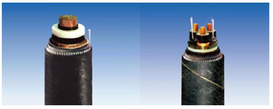
![Submarine optical fiber composite power cable[6]](/richHtml/gtxyj/2023/49/2/45/1005-8788-00-02-008-F001.jpg)
Fig. 1. Submarine optical fiber composite power cable[6]

Fig. 2. Cross-sectional view of cable
Fig. 3. Submarine cable model under tensile load[8]
Fig. 4. Fitting profile of strain for submarine cable to optical unit[11]
Fig. 5. Fitting curves of copper conductor stress and optical unite strain under different tensile load[8]
Fig. 6. Fitting profile of strain for copper conductor to optical unite[12]
Fig. 7. Stress-time curves at different positions of submarine cable[13]
Fig. 8. Submarine cable model under bending load
Fig. 9. Curves of copper conductor stress at different positions in different loading duration[16]
Fig. 10. Stress-time curves of copper conductor under different bending radius[17]
Fig. 11. Strain- angle curve of optical unite[18]
Fig. 12. Fitting curves of copper conductor/lead alloy stress and optical unite strain[18]
Fig. 13. Copper conductor stress at different positions[19]
Fig. 14. Submarine cable model under torsion load[9]
Fig. 15. Stress/strain-time curves of copper conductor in different torsion speed[20]
Fig. 16. Strain-time curves of optical unite in different torsion speed[21]
Fig. 17. Fitting curves of copper conductor stress and optical unite strain[21]
Fig. 18. Normalized optical strain/armored layer stress/armored layer plastic strain-time profile fitting results[11]
Fig. 19. Strain-time curves of optical unite under different impact angles[8]
Fig. 20. Normalized copper conductor stress/lead alloy stress/armored layer stress/optical strain-time profile fitting results[8]
Fig. 21. Stress-time curve of armored layer[29]
Fig. 22. Copper conductor plastic strain/optical unite strain-time curves[31]
Fig. 23. Displacement/acceleration-time fitting curve of optical unite[33]
Fig. 24. Vibration characteristics of optical unit in single-core submarine cable[34]

Set citation alerts for the article
Please enter your email address


