
Shengfu Cheng, Tianting Zhong, Woo Chi Man, Haoran Li, Puxiang Lai. Lensless Fiber-Optic Imaging via Coherent Light Modulation and Its Applications (Invited)[J]. Laser & Optoelectronics Progress, 2024, 61(6): 0618002
- Laser & Optoelectronics Progress
- Vol. 61, Issue 6, 0618002 (2024)

Fig. 1. Illustration of structures, refractive index distributions of fiber core and cladding, light propagation properties, and the supported propagation modes of representative optical fibers, where the red lines denote the light propagation inside the fiber cores and the rightest sides represent the electric field intensities of the supported modes for the corresponding optical fibers. (a) Step-index single-mode fiber; (b) step-index multimode fiber; (c) multicore step-index single-mode fiber (fiber bundle)
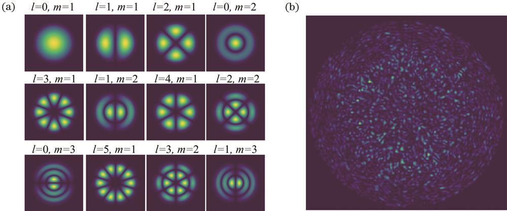
Fig. 2. Illustrations for fiber-optic mode theory and optical speckle.(a) Electric amplitude profile of the first 12 LP modes, where l and m are the order of the Bessel equation solution (radial) and the propagation constant solution (angular) respectively; (b) speckle pattern profile output by a multimode fiber
Fig. 4. Principles of spatiotemporal light field modulation in the field of lensless fiber-optic imaging. (a)-(d) Schematic of the principle of superpixel coding method[58], including the filtering aperture position on the spectrum plane of the 4f system, the 4×4 phase mask, the corresponding superpixel value on the complex-amplitude plane, and the complex-valued optical field that can be generated by the 4×4 superpixel; (e) LG10 mode amplitude; (f) LG10 mode phase; (g) CGH for encoding LG10 mode by superpixel method[58]; (h) CGH for encoding LG10 mode by Lee hologram[58]; (i) wavefront shaping allows a horizontally polarized light to retain its polarization state in a MMF or converts it to be vertically polarization for output[21]; (j) digital phase conjugation (DPC) for mitigating temporal broadening by MMF and achieving the transmission of focused 500 fs pulses[22]. Note the images from Refs.[22, 58] are reprinted with permission © Optica Publishing Group
Fig. 5. Schematic of several representative active wavefront modulation implementations used for lensless fiber-optic imaging. (a) Iterative wavefront optimization; (b) DOPC; (c) TM measurement via on-axis holography; (d) TM measurement via off-axis holography
Fig. 6. Representative works on lensless fiber-optic imaging based on wavefront optimization or conjugation. (a) Experimental setup of an MMF endoscope based on DOPC[83]; (b) neuron soma and dendrite fluorescence imaging results obtained from the device in Fig.6(a)[83]; (c) experimental setup of MCF wavefront optimization with proximal detection of 2PF signal as feedback[75]; (d) experimental results of the device in Fig.6(c) that include the optimized focusing result at fiber end (focal sidelobes originate from the periodic lattice of the fiber bundle), the curves of 2PF signal during optimization, the fluorescent object, and the object 2PF images[75]; (e) schematic of coherent MCF self-calibration using virtual "guide-star" and the measured phase distortion by MCF[66]; (f) imaging results of fluorescent particles at different depths from the distal facet of the self-calibrated MCF in Fig.6(e)[66]. Images are reprinted with permission from Refs.[66, 75, 83] © Optica Publishing Group
Fig. 7. Fiber calibration and minimally invasive endoscopic imaging results based on TM measurement. (a) Schematic of off-axis measurement of angular spectrum represented TM[95]; (b) schematic of off-axis measurement of TM based on incident focal spot on the MMF facet with phase shifts[91]; (c) typical experimental setup for MMF calibration and endoscopic imaging[61]; (d) imaging results of 4-μm fluorescent beads using wide-field microscopy and MMF endoscopy, respectively, where the scale is 20 μm[61]; (e) comparison of hippocampal neuron results obtained by confocal microscope and MMF endoscopy of mouse brain slices, where the scale is 20 μm[102]; (f) in vivo endoscopic imaging results obtained by implanting MMF into a mouse brain, including neuronal somata, processes, and haemorrhage images[64]; (g) lateral and axial point spread functions (PSF) of focusing for the calibrated MCF[103]; (h) incoherent wide-field imaging and coherent point scanning imaging results of 2-μm fluorescent beads before and after MCF calibration[103]. Note the images from Ref. [61, 91, 103] are reprinted with permission © Optica Publishing Group
Fig. 8. Lensless fiber-optic imaging methods based on passive object reconstruction. (a) TM-based method to recover objects from MMF output speckle pattern, including MSO operator, inverse of TM, and phase conjugate operator[105]; (b) TM-based MMF wide-field imaging method, including the reconstruction of speckle-encoded object at the end of the fiber and speckle average imaging[109]; (c) MCF speckle-correlation based wide-field imaging[25]; (d) MMF compressive imaging method with speckle illumination sequence[110]; (e) red blood cells and 11-μm fluorescent particles bright-field microscopic image and compressive reconstructed pseudo-color image, the scale bar is 30 μm[110]. Note the image from Refs.[25] is reprinted with permission © Optica Publishing Group
Fig. 9. Lensless MCF reflection imaging methods based on optical modelling. (a)(b) Schematic of quantitative phase imaging through MCF, and amplitude and phase image reconstruction of the 6th and 7th group elements of the resolution target, with the scale bar of 50 μm[32]; (c) (d) schematic of MCF Fourier holographic microscopic imaging, and images before and after correction for fiber-core phase retardation[33]; (e) (f) schematic of the distal holographic micro-endoscopic imaging, and results of on-focus amplitude and phase reconstruction of the resolution target[124]
Fig. 10. Multiple advanced lensless fiber-optic imaging modalities. (a) Schematic of MMF 3D confocal reflection imaging[125]; (b) reconstruction results at the front surface (120 μm away) and the back surface (320 μm away) of a coverslip from the end of the MMF using the setup in Fig.10(a)[125]; (c) MMF-based CARS images of 2.5 μm PMMA and 2 μm polystyrene particles over a series of frequency difference between the Stokes and pump beams[126]; (d) MMF-based linear polarization SHG imaging results of the mouse heart for three different positions (I pericardium, II ventricular wall, and III atrial wall)[127]; (e) simplified diagram of light sheet microscopy using a MMF, in which the sub-plots (I‒III) are in focus, and the subplots (IV‒VI) are defocused yz-plane profiles of the Gaussian (GB), Bessel (BB), and structured light Bessel (SI-BB) light sheets[128]; (f) schematic of PAM of red blood cells using an MMF[129]; (g) fluorescence intensity and lifetime imaging results of anesthetized mouse intestine based on MCF and their intensity and fluorescence lifetime values at the straight lines[130]; (h) cancer cell cytokinesis intensity image with a regular microscope (left), and amplitude (middle) and phase (right) distributions with MCF-based quantitative phase imaging[32]. Note the images from Ref. [125-127, 129-130] are reprinted with permission © Optica Publishing Group
Fig. 11. Recent advanced lensless fiber-optic imaging techniques. (a) Principle of MMF STABLE super-resolution imaging based on fluorescence emission difference and comparison of system PSF curves with and without STABLE[131-132]; (b) comparison of MMF images of fluorescent beads with conventional and STABLE techniques, with the scale bar of 0.5 μm[131]; (c) schematic of MMF holographic endoscope used for long-distance, time-of-flight imaging[134]; (d) depth image sequence recorded at different time for a revolving chessboard ~30 cm at the end of the fiber[134]; (e) schematic of phase modulation in a plane conjugate to the proximal fiber facet for achieving efficient far-field focusing through an MMF[133]; (f) illustration of a novel side-viewing MMF and its side-view imaging results of a resolution target[137]; (g) illustration of a twist MCF with conformational invariance and its two-photon imaging results of a test target in the bending state[138]; (h) schematic of lensless MCF light field imaging, including fiber geometry and the distal facet image (note different fiber cores correspond to different incident angles)[139]; (i) depth map of lens paper tissue with a lensless MCF[139]. Note some images are from Refs.[134, 139] © The Authors, some rights reserved; exclusive licensee AAAS. Distributed under a CC BY-NC 4.0 license, http://creativecommons.org/licenses/by-nc/4.0/ , reprinted with permission from AAAS; some images are reprinted with permission from Refs.[137-138] © Optica Publishing Group
|
Table 1. Types, characteristics, and typical applications of optical detectors used for lensless fiber-optic imaging
|
Table 2. Related applications of lensless fiber-optic imaging via coherent light modulation


Set citation alerts for the article
Please enter your email address

© Copyright 2018-2021 | Chinese Laser Press. All Rights Reserved 沪ICP备15018463号-20