
Munire TUERHONG, Honggang ZHAO, Yuhua MA, Xianhui QI, Yuchen LI, Chenxiang YAN, Jiawen LI, Ping CHEN. Construction and Photocatalytic Activity of Monoclinic Tungsten Oxide/Red Phosphorus Step-scheme Heterojunction [J]. Journal of Inorganic Materials, 2023, 38(6): 701
- Journal of Inorganic Materials
- Vol. 38, Issue 6, 701 (2023)
Abstract
Red phosphorous (RP) is one of the most abundant, inexpensive, less toxic, and easily available materials[1⇓-3]. It possesses strong visible light absorption, and has great potential for photocatalytic applications[4]. However, the photogenerated electron and hole are easily recombined in photocatalytic efficiency, which greatly limits its application because of RP large particle size and agglomeration[5]. RP is combined with other semiconductor material to construct heterojunction, which can effectively overcome the above disadvantages and improve the photocatalytic activity[6], such as SnO2/RP[7], Bi2O3/RP[8], Bi2O2CO3/RP[9], g-C3N4/RP[10] and Bi2Fe4O9/RP[11]. Therefore, it is necessary to find suitable semiconductor matching RP to build heterojunction.
Tungsten trioxide (WO3), as a typical n-type semiconductor with narrow bandgap energy (2.4-2.8 eV)[12], was widely used in the management of environmental remediation[13]. Although remarkable advances have been made, the narrow band gap of WO3 also causes fast recombination rate of photo-induced charges, leading to poor photocatalytic activity[14-15]. Compared with pure WO3 and RP, WO3/RP composite showed better hydrogen evolution, which could reduce the recombination of charge carriers[16]. However, WO3/RP composites via a low temperature calcination method led to aggregation and decrease of the active sites of RP.
In this study, the WO3/HRP S-scheme heterojunction was constructed through hydrothermal treatment. The photocatalytic performance was estimated by photocatalytic organic degradation and hydrogen evolution. Finally, the S-scheme heterojunction photocatalytic mechanism of WO3/HRP composites was directly evidenced by in situ X-ray photoelectron spectroscopy (XPS) and electron paramagnetic resonance (EPR) results.
1 Experimental
1.1 Preparation of WO3/HRP composite
1.2 Photocatalytic pollutant degradation
A 300 W Xe lamp (UV light was cutoff-filtered, 140 mW/cm2) was used, and RhB was used as target pollutant. 5 mg photocatalyst was added into 20 mL RhB solution (10 mg·L-1), and then stirred in dark for 30 min to ensure absorption-desorption equilibrium. During the irradiation process, the suspension was removed every 1 min for centrifugation and the absorbance of the residual RhB solution was determined by UV-Vis spectrophotometer at the maximum absorption wavelength (λmax=554 nm).
1.3 Photocatalytic hydrogen evolution
Photocatalytic hydrogen production was carried out by using a 300 W Xe lamp (UV light was cutoff-filtered, 140 mW/cm2). The generated hydrogen was in situ detected periodically using an online gas chromatography (GC-7900) with a thermal conductivity detector. 50 mg photocatalyst was dispersed in 80 mL solution containing Na2SO3 (0.35 mol·L-1) and Na2S (0.15 mol·L-1) as the sacrifice agent, and the suspension was magnetically stirred under visible light irradiation.
2 Results and discussion
2.1 Photocatalyst characterization
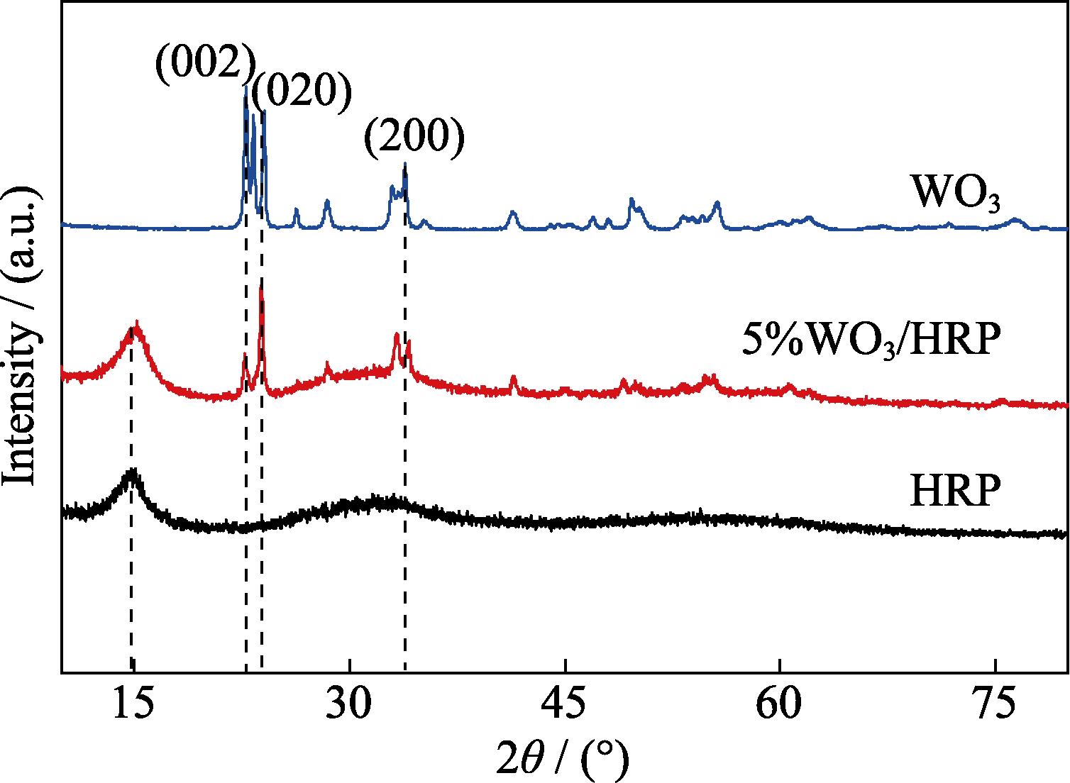
The crystal structures of the HRP, WO3 and 5%WO3/HRP composite were analyzed by XRD patterns (Fig. 1). For pure HRP, the characteristic diffraction peak at 2θ=14.9° corresponded to (102) crystal plane, consistent with the reported results in the literature[17]. The characteristic peaks of WO3 indexed at 2θ=22.8°, 24.1°, and 33.9° correspond to the planes (002), (020) and (200) facets (JCPDS 83-0951), according to the lattice parameters of monoclinic tungsten oxide[18⇓-20]. For 5%WO3/HRP composite, the diffraction peaks of the HRP and WO3 were obviously present.
![]()
Figure 1.XRD patterns of HRP, WO3 and 5%WO3/HRP composite
The surface chemical compositions of all samples were characterized by FT-IR spectroscopy (Fig. S1). For pure HRP, the vibration absorption of the P-P-O, P-O and P=O bond located at 1008, 1178 and 1641 cm-1, which was consistent with the characteristic absorption peaks of RP[21]. For pure WO3, the absorption peaks at 956, 823 and 753 cm-1 were referred to W=O, O-W-O and W-O-W bonds[22]. The characteristic peaks of WO3 and HRP functional groups were presented in the FT-IR spectrum of 5%WO3/HRP, indicating the coexistence of WO3 and HRP in the composite.
The morphologies of as-prepared samples were examined by SEM. HRP removed impurities from the surface of commercial RP, and its surface existed micropore (Fig. S2(a, d)). The typical morphology of WO3 was rectangular nanoplates with a certain thickness (Fig. S2(b, e)). 5%WO3/HRP composite revealed a large number of loose particles, which facilitates the improved light adsorption, and also provides abundant spaces for the anchoring of other particles (Fig. S2(c, f)). Furthermore, the basic elements of W, O, and P were present in the WO3/HRP composite (Fig. S2(g, h). Thus, HRP and WO3 coexisted in the WO3/HRP composites.
The crystal structure and lattice orientation of each sample were further investigated through TEM. HRP surface was amorphous, and tiny folded, which was favorable to its surface adsorption properties (Fig. 2(a, b)). The WO3 nanostructure exhibited regular sheet-like morphology structure, which was consistent with the SEM results (Fig. S2(c)). The lattice size was 0.37 nm that matched the distance (020) planes of monoclinic WO3 structure, according to the lattice parameters of monoclinic WO3 (JCPDS 83-0951)[18]. TEM images of 5%WO3/HRP showed that there was an additional layer of homogeneous WO3 on the surface of HRP and closely connected to each other, avoiding aggregation of HRP and forming a heterogeneous structure that facilitates interfacial charge transfer (Fig. 2(e, f)).
![]()
Figure 2.TEM images of (a, b) HRP, (c, d) WO3 and (e, f) 5%WO3/HRP composite
XPS survey spectra were conducted to investigate the chemical compositions and bonding configurations of the samples[23]. C, O, P and W were present in the composite (Fig. S3(a)). The high-resolution P2p spectrum of HRP (Fig. 3(a)) was deconvoluted into two peaks at 129.82 and 130.61 eV, corresponding to P2p3/2 and P2p1/2, respectively, and the binding energy peak at 134.19 eV corresponded to P-O bond, indicating the presence of phosphorus oxides on the surface of HRP. While in 5%WO3/HRP composite, the P-O bond disappeared and the binding energies of the P2p3/2 and P2p1/2 were shifted towards higher binding energy, 130.12 and 130.97 eV, respectively, indicating that combination can prevent further oxidation of HRP. The W4f region of WO3 (Fig. 3(b)) was divided into two peaks at 35.52 and 36.33 eV, assigned to W4f5/2 and W4f7/2 orbitals of W5+. Another two peaks at 37.66 and 38.32 eV were corresponded to the W4f5/2 and W4f7/2 orbitals of W6+. W5+ was derived from the unsaturated W-O bonds on the surface of WO3. The presence of W5+ indicated the exfoliation of bulk WO3 into ultrathin WO3 nanosheets. The binding energy at 41.63 eV was associated with W5f3/2[24]. While, the binding energies of W4f5/2 and W4f7/2 in the 5%WO3/HRP composite shifted to low binding energy, and the ratio of W6+/W5+ increased, which facilitated its energy conversion. Thus, when HRP was closely contacted with WO3, the electrons could flow into WO3 from HRP though the interface. Therefore, the heterojunction was formed between WO3 and HRP, leading to strong electronic interaction.
![]()
Figure 3.(a) P2p and (b) W4f XPS spectra of samples
2.2 Photocatalytic performance
2.2.1 Photocatalytic degradation
The photodegradation performance of these catalysts was tested under visible light irradiation with RhB as the target pollutant (Fig. 4(a)). The equilibrium state of adsorption-desorption between the photocatalyst and the target pollutant was achieved after 30 min of reaction in the dark. Obviously, WO3/HRP composites showed better adsorption capacity for RhB. Under visible light condition, the photodegradation performance of WO3/HRP composites were higher than those of HRP and WO3, and 5%WO3/HRP composite was demonstrated the highest photocatalytic activity, and its removal rate reached 97.6% after 4 min. However, with further increasing of the WO3/HRP ratio, the photocatalytic performance decreased since the excess WO3 hinder the transfer of photogenerated carriers and reduce the exposure of active sites.
![]()
Figure 4.(a) Photodegradation curves, (b) rate curves, and (c) hydrogen production rates of HRP, WO3, 3%WO3/HRP, 5%WO3/HRP, and 7%WO3/HRP composites
The photodegradation reactions of RhB in the synthesized samples conformed to the pseudo-first-order reaction model (Fig. 4(b)):
where k is the rate consistent (min−1), C0′ is the concentration of pollutants in the equilibrium of adsorption- desorption, and Ct is the concentration of contaminants for the remaining time after irradiation. The k of HRP, WO3, 3%WO3/HRP, 5%WO3/HRP and 7%WO3/HRP were 0.17, 0.01, 0.68, 0.75 and 0.69 min-1, respectively. Among them, the k of 5%WO3/HRP composite was highest, which was 4.5 and 75 times of those of HRP and WO3. Therefore, the formation of heterojunction could enhance the photocatalytic activity. Furthermore, after five cycles of photocatalytic degradation of RhB, 5%WO3/HRP composite still had high photocatalytic activity (90.4%), showing good stability with practical application potential.
2.2.2 Photocatalytic hydrogen evolution
The photoreduction ability of HRP, WO3 and WO3/HRP composites were examined by photocatalytic water splitting into hydrogen. HRP possessed a relatively low photocatalytic activity with hydrogen production rate of 240.5 μmol·h-1·g-1, and the pure WO3 was almost absent, whereas a sharp increase in the rate of hydrogen production was observed in the WO3/HRP composite (Fig. 4(c)). Fascinatingly, the hydrogen evolution rate of 5%WO3/HRP composite was 870.69 μmol·h-1·g-1, which was 3.62 times of that of pure HRP. The apparent quantum efficiency (AQE) was calculated according to the following formula[26]:
Where NA is the Avogadro’s constant (6.02×10²³ mol-1), M is the average H2 generation rate (mol·s-1), E is power of lamp source, h is the Plank’s constant (6.626×10⁻³⁴ J·s), λ is the excitation wavelength, and c is the speed of light (3.0×10⁸ m·s-1).
AQE of 5%WO3/HRP composite was calculated to be 11.61%. Further increasing the amount of WO3 beyond 5% lead to a decrease in photocatalytic hydrogen evolution rate, which could originate from shielding of the light absorption by excess amount of WO3. Therefore, appropriate WO3 content had a remarkable effect on the activity enhancement of WO3/HRP composite.
The above RhB photodegradation and photocatalytic hydrogen evolution results exhibited that the 5%WO3/ HRP composite possessed superior photocatalytic activity. The introduction of appropriate WO3 content inhibits the overgrowth and agglomeration of HRP, and the heterojunction between WO3 and HRP promotes the separation of electrons and holes and accelerates the carrier migration.
2.3 Catalyst mechanism analysis
The optical absorption properties of prepared samples were investigated by UV-Vis DRS (Fig. 5(a)). HRP had significant absorption of visible light, meaning it was typical visible light photocatalytic material. For pure WO3, the absorption edge was located at around 446 nm. Compared with pure WO3 and HRP, the 5%WO3/HRP composite had a red-shifted absorption edge, which illustrated enhancement of absorption in both UV and IR regions. The UV-visible light absorption performance of 5%WO3/HRP composite combined the advantages of two materials, which successfully formed a heterojunction, and enhanced light-trapping ability. The band gap (Eg) values of the pure HRP and WO3 were obtained through transformation with Kubella-Munk function, and were 1.9 and 2.78 eV, respectively (Fig. 5(b)).
![]()
Figure 5.(a) UV-Vis DRS spectra of HRP, WO3 and 5%WO3/HRP composite, (b) Tauc plots of HRP and WO3, and (c)
The generation, migration, and recombination processes of photocarriers were investigated by PL spectra, transient photocurrent (I-t) curves and electrochemical impedance spectroscopy (EIS) measurements[29]. The 5%WO3/HRP composite had lower PL signal, indicating lower recombination of photoinduced electrons and holes (Fig. S3(c)). In addition, the photocurrent signal intensity of the 5%WO3/HRP composite was 3.3 μA/cm2, which was 4~5 times of those of HRP (0.8 μA/cm2) and WO3 (0.7 μA/cm2), respectively (Fig. 5(c)). These results implied that the lifetime of the photoexcited electron-hole pairs was significantly prolonged due to the more efficient separation, after combining HRP with WO3.
The arc radius of 5%WO3/HRP composite was smaller than those of HRP and WO3, indicating the minimum charge impendence and the fastest reaction speed (Fig. 6(a)). This finding was consistent with the higher photocatalytic activity of the 5%WO3/HRP composite due to the tight interface between WO3 and HRP, which promoted carrier separation migration. Similarly, the equivalent circuit was analyzed to provide more intuitive understanding of the internal charge and surface charge- transfer mechanism of the catalyst during the reaction (insert in Fig. 6(a)). Here, R1 and R2 were denoted as the electrolyte solution and charge transfer resistances, which included the resistances of the photocatalyst, ITO substrate, electrolyte solution, and wire connections throughout the circuit. CPE1 was the constant phase element that represents the bilayer capacitance of the charge transfer, and W1 was the resistance with interfacial diffusion. R1 of HRP, WO3 and 5%WO3/HRP were 10.1, 11.71 and 12.53 Ω, respectively. Under the same concentration, R2 of HRP, WO3, HRP and 5%WO3/HRP were 672, 167 and 93.4 Ω, respectively. Obviously, the interfacial charge resistances of heterojunction composites were lower, indicating easier charge transfer. Therefore, the superior photocatalytic activity of 5%WO3/HRP composite contributed to the highest photoelectric conversion efficiency, smaller interfacial transfer impendence and enhanced visible light absorption ability. The carrier lifetime (τe) of samples are based on the EIS bode plots (Fig. S4(a, b)), proving the carrier transfer process, according to the equation[30]:
![]()
Figure 6.(a) EIS spectra of HRP, WO3 and 5%WO3/HRP composite, (b) Mott-Schottky curves of HRP and WO3, and (c) EPR spectra of HRP, WO3 and 5%WO3/HRP composite
where fmax is the maximum frequency peak position, the calculated τe of the HRP and 5%WO3/HRP composite were 1.68 and 2.7 ms, respectively. The carrier lifetime of 5%WO3/HRP heterostructure composite was much longer than those of pure HRP, suggesting that the formation of the heterostructure between HRP and WO3 could greatly prolong the lifetime of the photo-generated electrons, and enhanced the photocatalytic activity.
2.4 Photogenerated carrier analysis
The energy band structures of samples were revealed by Mott-Schott (M-S) measurements (Fig. 6(b)). The flat potentials (Efb) of HRP and WO3 were -0.8 and -0.66 V (vs. Ag/AgCl), respectively, and then converted to the hydrogen standard electrode potential based on the formula:
Where EAgCl is 0.197 V, and pH of the electrolyte was 6.8. Here, Efb (vs. NHE) of HRP and WO3 were -0.2 and -0.06 V, respectively. The slopes of WO3 and HRP curves were positive, both samples were n-type semiconductors, and Efb is 0.1-0.3 V higher than its conduction band potential (ECB). Therefore, the ECB of HRP and WO3 were -0.4 and -0.26 V (vs. NHE). In accordance with the formula: Eg = EVB-ECB, the EVB were 1.5 and 2.52 V, respectively.
The hydroxyl radicals (·OH) was important species in the photocatalytic reactions, EPR spectra were presented in Fig. 6(c). HRP had relatively weak signal because of the weak oxidation potential of photogenerated holes, WO3 displayed moderately strong signal due to its more positive EVB, and 5%WO3/HRP composite had strong DMPO-·OH signal, so the photogenerated holes remained in WO3 and did not transfer to the VB of HRP. Because the potential of OH-/·OH pair was +2.38 V (vs. NHE)[31], which was positive than that of HRP (+1.5 V (vs. NHE)) and negative than that of the WO3 (+2.52 V (vs. NHE), inferring that the ·OH radical was produced by WO3. These results indicated that the photogenerated electrons and holes in 5%WO3/HRP composite were present in the CB of HRP and VB of WO3, respectively, and the charge transfer belonged to S-scheme heterojunction.
Based on above discussions, the S-scheme mechanism was proposed in Fig. 7. HRP is a reducing photocatalyst with smaller work function (5.61 eV)[17] and higher Fermi level. WO3 is an oxidizing photocatalyst with large work function (6.23 eV)[32] and lower Fermi level (Fig. 7(a)). When the WO3 photocatalysts was in close contact with HRP, electrons spontaneously transferred from HRP to WO3 until their Ef reached the same level. During the migration of electrons, the interface region of WO3 possesses a positive charge due to the loss of electrons, which leads to the formation of electron depletion layer and the upward bending of the energy band. While interface region near the HRP is negatively charged due to the gain of electrons, which leads to the formation of an electron accumulation layer and the downward bending of the band edge. As a result, an internal electric field is formed at the interface of the WO3/HRP heterojunction, impeding the continuous flow of electrons from HRP to WO3 (Fig. 7(b)). Under visible light irradiation, the electrons were excited from VB to CB of WO3 and HRP. Driven by the internal electric field, band bending and Coulomb interaction, the photogenerated electrons in the CB of WO3 spontaneously slid toward HRP, and recombined with the holes on the VB of HRP. However, the useful electrons and holes of strong redox ability could be retained (Fig. 7(c)). Therefore, the improved photocatalytic performance of the WO3/HRP composite was mainly ascribed to the formation of S-scheme heterojunctions, which contribute to the strong redox capacity for the degradation of organic water pollutants and hydrogen generation.
![]()
Figure 7.Photocatalytic mechanism of the WO3/HRP composite(a) Before contact; (b) After contact in darkness; (c) S-scheme transfer process of photogenerated carriers under visible light irradiation
3 Conclusions
In this study, the S-scheme WO3/HRP heterojunction photocatalysts were prepared by the hydrothermal method. The heterojunctions displayed significantly enhanced photocatalytic RhB degradation and hydrogen evolution. The 5%WO3/HRP heterojunction photocatalysts degraded 97.6% RhB within 4 min. Meanwhile, the photocatalytic hydrogen evolution was almost 3.62 times of pure HRP. The enhanced photocatalytic performance was attributed to the S-scheme heterojunction between WO3 and HRP, which effectively transferred the photo-generated carriers, and suppressed the recombination of electron-hole pairs. This work could provide new prospect for design and construction of novel heterojunction photocatalyst.
References
[13] J ZHANG, Z LIU, Z LIU. Novel WO3/Sb2S3 heterojunction photocatalyst based on WO3 of different morphologies for enhanced efficiency in photoelectrochemical water splitting. ACS Applied Materials & Interfaces, 8, 9684(2016).


Set citation alerts for the article
Please enter your email address

© Copyright 2018-2021 | Chinese Laser Press. All Rights Reserved 沪ICP备15018463号-20