• Laser & Optoelectronics Progress
  • Vol. 59, Issue 23, 2312005 (2022)
Tao Jiang1,2,*, Haihua Cui2, Xiaosheng Cheng2, and Wei Tian2
Author Affiliations
  • 1School of Mechanical and Electrical Engineering, Suqian University, Suqian 223800, Jiangsu, China
  • 2College of Mechanical and Electrical Engineering, Nanjing University of Aeronautics and Astronautics, Nanjing 210016, Jiangsu, China
  • show less
    DOI: 10.3788/LOP202259.2312005 Cite this Article Set citation alerts
    Tao Jiang, Haihua Cui, Xiaosheng Cheng, Wei Tian. Combined Optical Scanning Transposition Pose Calibration Method Integrating Scale Factor[J]. Laser & Optoelectronics Progress, 2022, 59(23): 2312005 Copy Citation Text show less
    Geometrical model of combined optical tracking and scanning
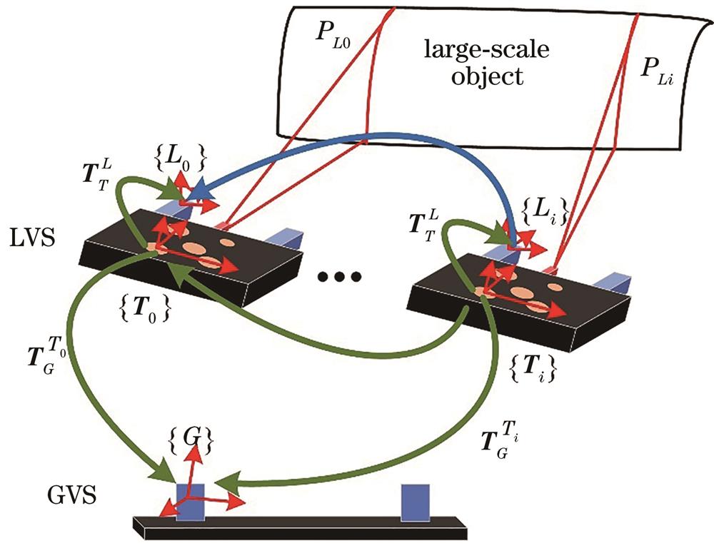
    Fig. 1. Geometrical model of combined optical tracking and scanning
    Variation curves of TGT and PG errors corresponding to accuracy ratio of GVS and LVS. (a) Rotation matrix of TGT; (b) translation vector of TGT; (c) relative error of PG
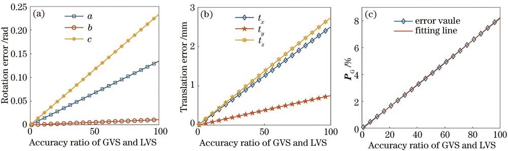
    Fig. 2. Variation curves of TGT and PG errors corresponding to accuracy ratio of GVS and LVS. (a) Rotation matrix of TGT; (b) translation vector of TGT; (c) relative error of PG
    Simulation of transposition pose calibration. (a) Visualization platform; (b) data transmission route
    Fig. 3. Simulation of transposition pose calibration. (a) Visualization platform; (b) data transmission route
    Experiment of transposition pose calibration. (a) Experimental setup; (b) calibration board; (c), (d) target detection results of GVS view; (e), (f) target detection results of LVS view
    Fig. 4. Experiment of transposition pose calibration. (a) Experimental setup; (b) calibration board; (c), (d) target detection results of GVS view; (e), (f) target detection results of LVS view
    Evaluation of scanning accuracy using standard plane
    Fig. 5. Evaluation of scanning accuracy using standard plane
    Scanning accuracy comparison of proposed method with commercial device. (a) Blade 1 without scale factor; (b) blade 1 with scale factor; (c) blade 2 without scale factor; (d) blade 2 with scale factor
    Fig. 6. Scanning accuracy comparison of proposed method with commercial device. (a) Blade 1 without scale factor; (b) blade 1 with scale factor; (c) blade 2 without scale factor; (d) blade 2 with scale factor
    Scale factor setting valueScale factor calibration valueScale factor errorRotation matrix error /%Translation vector error /%
    1.01.0000.340.076
    1.11.120.020.360.081
    1.21.230.030.380.098
    1.31.280.020.450.110
    1.41.440.040.480.120
    1.51.470.030.520.160
    1.61.640.040.550.130
    1.71.670.030.600.150
    1.81.850.050.640.160
    1.91.950.050.680.180
    2.02.060.060.750.230
    Table 1. Calibration result error with scale change
    Calibration circle P¯Gj1234Average standard error
    Standard error /mm0.080.110.120.090.10
    Table 2. Combined calibration error
    Tao Jiang, Haihua Cui, Xiaosheng Cheng, Wei Tian. Combined Optical Scanning Transposition Pose Calibration Method Integrating Scale Factor[J]. Laser & Optoelectronics Progress, 2022, 59(23): 2312005
    Download Citation