• Laser & Optoelectronics Progress
  • Vol. 60, Issue 15, 1512001 (2023)
Ziyong Ma1,2,*, Fuquan Zhang1, Lidong Ma1, Hechen Ma1, and Jiahao Hang2
Author Affiliations
  • 1School of Mechanical Engineering, Taiyuan University of Science and Technology, Taiyuan 030024, Shanxi, China
  • 2High-End Equipment and Rail Transit Technology R&D Center of Haian Taiyuan University of Science and Technology, Haian226600, Jiangsu, China
  • show less
    DOI: 10.3788/LOP221868 Cite this Article Set citation alerts
    Ziyong Ma, Fuquan Zhang, Lidong Ma, Hechen Ma, Jiahao Hang. Line-Structured Light Based Micro-Irregular Component Geometric Dimension Measurement Method[J]. Laser & Optoelectronics Progress, 2023, 60(15): 1512001 Copy Citation Text show less
    Composition of the measuring system
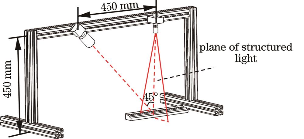
    Fig. 1. Composition of the measuring system
    Image of profile of micro irregular component
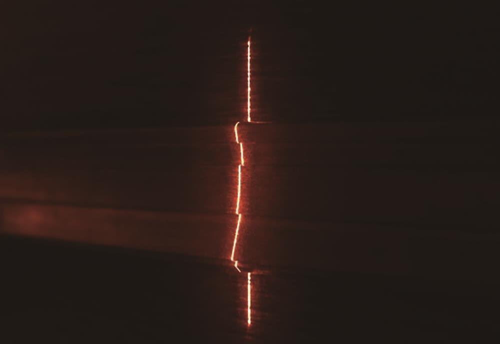
    Fig. 2. Image of profile of micro irregular component
    Camera imaging model
    Fig. 3. Camera imaging model
    Line-structured light. (a) Original image of line-structured light; (b) Steger thinning image of line-structured light
    Fig. 4. Line-structured light. (a) Original image of line-structured light; (b) Steger thinning image of line-structured light
    Mathematical model of line-structured light
    Fig. 5. Mathematical model of line-structured light
    Selection of central feature points of line-structured light
    Fig. 6. Selection of central feature points of line-structured light
    Least square fitting plane
    Fig. 7. Least square fitting plane
    Distance between fitting points and line-structured light plane
    Fig. 8. Distance between fitting points and line-structured light plane
    Height measurement of different gauge blocks. (a) Original heights; (b) height measurements; (c) standard deviations of repeated measurement error in height
    Fig. 9. Height measurement of different gauge blocks. (a) Original heights; (b) height measurements; (c) standard deviations of repeated measurement error in height
    Width measurement of different gauge blocks. (a) Original widths; (b) width measurements; (c) standard deviations of repeated measurement error in width
    Fig. 10. Width measurement of different gauge blocks. (a) Original widths; (b) width measurements; (c) standard deviations of repeated measurement error in width
    Measurement test of No. 1 micro irregular component. (a) Original image of the component; (b) position of geometric points; (c) dimension measurement of different parts of the component; (d) geometric dimension error of the component
    Fig. 11. Measurement test of No. 1 micro irregular component. (a) Original image of the component; (b) position of geometric points; (c) dimension measurement of different parts of the component; (d) geometric dimension error of the component
    Measurement test of No. 2 micro irregular component. (a) Original image of the component; (b) position image of geometric points; (c) dimension measurement of different parts of the component; (d) geometric dimension error of the component
    Fig. 12. Measurement test of No. 2 micro irregular component. (a) Original image of the component; (b) position image of geometric points; (c) dimension measurement of different parts of the component; (d) geometric dimension error of the component
    Measurement test of No. 3 micro irregular component. (a) Original image of the component; (b) position image of geometric points; (c) dimension measurement of different parts of the component; (d) geometric dimension error of the component
    Fig. 13. Measurement test of No. 3 micro irregular component. (a) Original image of the component; (b) position image of geometric points; (c) dimension measurement of different parts of the component; (d) geometric dimension error of the component
    Internal parameterfxfyu0v0k1k2
    Value10727.1845410665.964101959.577241437.57213-0.062884.67621
    Table 1. Internal parameters of industrial camera
    ParameterαCβCγCδC
    Value-0.995530.02163-1.00000571.89965
    Table 2. Plane equation coefficients of line-structured light
    ParameterAverage deviationStandard deviationRMS
    Value /mm0.0530.0410.067
    Table 3. Fitting accuracy evaluation of line-structured light plane
    Block number1#2#3#4#5#6#7#8#9#10#11#
    Actual thickness value /mm1.0001.0601.1001.3001.5001.7002.0003.0004.0006.00010.000
    Table 4. Actual thickness value of eleven gauge blocks
    Block numberTrue value /mmResult of proposed method /mmResult of multi-line fitting method /mm
    WidthHeightWidthHeightWidthHeight
    1#8.9001.0008.9281.0158.9751.086
    2#8.9001.0608.8471.0088.8831.158
    3#8.9001.1008.9541.1418.9741.171
    4#8.9001.3008.9251.2688.8191.389
    5#8.9001.5008.8411.5318.9701.586
    6#8.9001.7008.8381.7358.8131.792
    7#8.9002.0008.9711.9718.9632.094
    8#8.9003.0008.9882.9768.9503.095
    9#8.9004.0008.9763.9378.9854.080
    10#8.9006.0008.8475.9478.9976.084
    11#8.90010.0008.9639.9418.80110.068
    Table 5. Comparison of maximum measurement error of gauge blocks
    Ziyong Ma, Fuquan Zhang, Lidong Ma, Hechen Ma, Jiahao Hang. Line-Structured Light Based Micro-Irregular Component Geometric Dimension Measurement Method[J]. Laser & Optoelectronics Progress, 2023, 60(15): 1512001
    Download Citation