【AIGC One Sentence Reading】:We propose an all-fiber OAM mode encoding system using helical fiber gratings, featuring low cost, loss, and high efficiency.
【AIGC Short Abstract】:We propose an all-fiber OAM mode encoding system using helical fiber gratings, encoding/decoding binary symbols into OAM modes with TCs of ±1. The system is cost-effective, has low insertion loss, high conversion efficiency, and is polarization-independent, marking a novel approach for optical and quantum communication.
Note: This section is automatically generated by AI . The website and platform operators shall not be liable for any commercial or legal consequences arising from your use of AI generated content on this website. Please be aware of this.
Abstract
In this study, we propose and demonstrate an all-fiber orbital-angular-momentum (OAM) mode encoding system, where through helical fiber gratings (HFGs), binary symbols are encoded to or decoded from two OAM modes with topological charges (TCs) of and , respectively. We experimentally validate that the OAM mode generated by a clockwise-helix HFG (cHFG) can be converted back into fundamental mode by using an HFG with a helix orientation opposite to that of the cHFG, i.e., ccHFG. Benefited from utilization of the HFGs, the proposed OAM mode encoding system has a low cost, low insertion loss, high mode conversion efficiency, and polarization independence. To the best of our knowledge, this is the first demonstration of the HFGs-based all-fiber OAM mode encoding/decoding scheme, which may find potential applications in optical communication and quantum communication as well.
1. INTRODUCTION
Orbital-angular-momentum (OAM) beams with helical phase fronts, as a new freedom resource of photons, have attracted extensive attention over the past decades [1]. To date, OAM beams have found various applications in the fields such as optical communication [2–6], optical manipulation [7–9], optical sensing [10], optical imaging [11–13], and quantum science [3,14] capacity and performance of optical/quantum communication systems [15,16], since the OAM modes with different topological charges (TCs) are orthogonal to each other [17]. Two scenarios for OAM-beams-based communication systems have been proposed and widely studied, which include the mode multiplexing and the mode encoding ones. In an OAM multiplexing system, different OAM beams carrying information of channels were multiplexed at a transmitter, co-propagated in the same medium, and de-multiplexed at a receiver. Such OAM mode multiplexing technique can greatly increase the capacity of optical communication systems [8], whereas in an OAM encoding system, each symbol is encoded (modulated) in one of the different OAM modes at a transmitter, and decoded (demodulated) at a receiver. Such OAM mode encoding technique is especially suitable for demonstration of the quantum communication where the photons in general are rich in dimensional resources. However, in all the OAM multiplexing and encoding fiber communication systems reported to date, bulky optical components, such as a spatial light modulator (SLM), spiral phase plate (SPP), and vortex retarder (VR), are generally required to convert the fundamental mode to OAM modes and vice versa, which inevitably increases the size, the cost, and the insertion loss and great care must be paid to alignment of the system. In addition, most of the utilized bulky components have polarization dependence, which would in turn restrain the bulky system from the practical applications. Today, to develop an all-fiber OAM encoding/decoding system that has polarization independence is strongly required.
Owing to their superior characteristics, such as the compact size, extremely low cost, low insertion loss, high conversion efficiency, and inherent compatibility with other fiber devices, the fiber-grating-based OAM generators, which can convert fundamental mode into OAM modes, have recently attracted a significant research interest [18]. However, some additional components, which are used to introduce a constant phase difference between the even and odd fiber modes, are generally demanded, inevitably bringing much more insertion and polarization-dependent losses. To address the above issue, the helical fiber gratings (HFGs) inscribed in single-mode fibers (SMFs) [19], few-mode fibers (FMFs) [20], ring-core fibers (RCFs) [21], and photonic-crystal fibers (PCFs) [22] have been proposed and experimentally demonstrated, which have already been used to produce the first- to sixth-order OAM modes. However, the conversion from the higher-order OAM modes to fundamental mode has never been demonstrated in HFGs or other fiber-based devices.
In this study, firstly we experimentally prove that the OAM modes generated by a clockwise-helix HFG (cHFG), can be converted back into fundamental mode by using an HFG but with a helix orientation opposite to that of the cHFG (ccHFG). Then based on the above proof, we have proposed and demonstrated an all-fiber OAM encoding/decoding system, where by using the HFGs, binary symbols are encoded to or decoded from OAM modes with TCs of and . Thanks to the use of all-fiber devices, the proposed system has the advantages of compact size, low loss, and compatibility with other fiber-based systems. To the best of our knowledge, this is the first demonstration of an all-fiber OAM encoding/decoding system, which may find potential applications in optical communication and quantum communication as well.
Sign up for Photonics Research TOC. Get the latest issue of Photonics Research delivered right to you!Sign up now
2. PRINCIPLES FOR OAM MODES CONVERTER
Attributed to either the eccentric core of the originally utilized fiber or the imperfect cylindrical symmetry of the HFGs generated during the fiber twisting process, the refractive index modulation Δ for -helix HFGs in general can be expressed as [23–25] where represents the axial position along the HFG, and and represent the radial and azimuthal directions, respectively. represents the maximum refractive index modulation induced by twisting the optical fiber. represents the helical direction of the HFG. More specifically, and represent HFGs with the clockwise (cHFG) and counterclockwise (ccHFG) helix (twist) orientations, respectively. represents the helix or the number of angular symmetries in the HFGs, which is considered to be for the single-helix HFG used in this study. denotes the period of the HFG. and represent the order and Fourier coefficients of the harmonics, respectively. To couple (convert) the fundamental mode () to the higher-order OAM mode with the same polarized state, where the first subscript represents the azimuthal (OAM) order, also called the topological charge, and the second subscript represents the radial order, for resonant coupling occurring in an HFG, the following phase and OAM-matching equations must be satisfied [23]: where and represent the effective indexes of the input fundamental mode and the coupled output OAM mode, respectively. and represent the resonant wavelength and the period of the HFG. and are the TCs of the fundamental mode () and the coupled output higher-order azimuthal (OAM) mode (), respectively. Equations (2) and (3) mean that OAM modes with TCs of and can be obtained from the input fundamental modes just by using the -order of the cHFG and the ccHFG, respectively, without the need of any additional components, such as the polarization controller (PC), which is generally used to introduce a constant phase difference between the even and odd modes.
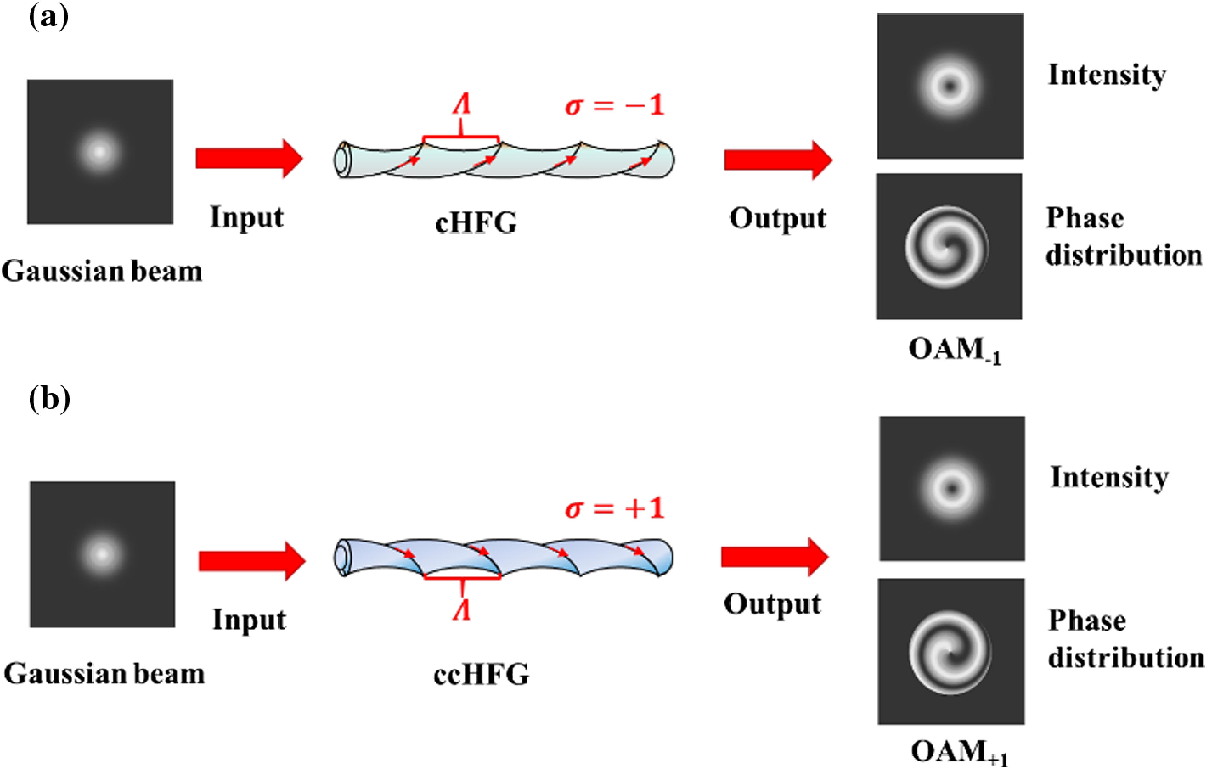
Figures 1(a) and 1(b) show that OAM modes with TC of () and TC of () can be converted (generated) from input fundamental modes using the mode coupling relations expressed as Eqs. (2) and (3) for cHFG and ccHFG, respectively, where only the first-order harmonic of is considered. Based on such mode coupling relations, the polarization-independent first- to third-order OAM modes have been produced to date [25–30]. However, whether the generated OAM modes can be converted back into fundamental modes using fiber-based devices has never been proved, which is essential for all-fiber OAM multiplexing and encoding systems.
Figure 1.The principle scheme of an HFG for generation of the OAM modes from the fundamental mode. (a) The OAM mode with TC of obtained by using a cHFG and (b) the OAM mode with TC of obtained by using a ccHFG.
Similar to the phase and OAM matching conditions obeyed in HFGs, i.e., Eqs. (2) and (3), the phase and OAM matching condition for converting OAM modes back into fundamental modes can be expressed as where and represent the effective indexes of the coupled output fundamental mode and the input OAM mode, respectively. and are the TCs of the fundamental mode () and the input OAM mode, respectively. Equations (4) and (5) show that the OAM modes, which are generated using the HFGs with the helix orientation , can be converted back into fundamental modes using the HFGs with the opposite helix orientations () and the same period . Figure 2 shows the principle scheme for converting the OAM modes back to the fundamental mode, where Figs. 2(a) and 2(b) show that the input OAM modes with TC of () and TC of () can be converted back into the output fundamental modes using ccHFG and cHFG, respectively, which has never been demonstrated before.
Figure 2.The principle scheme for converting the OAM modes back to the fundamental mode. Fundamental mode obtained from (a) the OAM mode with TC of by using a ccHFG and (b) the OAM mode with TC of by using a cHFG.
Figure 3 shows the experimental setup for fabrication and monitoring spectra of the HFGs, which mainly consists of a laser (Synrad, FSTI60SFH), three motorized translational stages (Thorlabs, LTS300/M), and a motorized rotator (Thorlabs, DDR25/M). In addition, a wideband light source (YSL, SC-5) and an optical spectrum analyzer (OSA) (Yokogawa, AQ6370) were used to monitor the transmission spectra of the fabricated HFGs. During the fabrication process, both ends of the utilized fiber were fixed at a clamp (located on stage 3) and center of the rotator (located at stage 2), as shown in Fig. 3. By using a sapphire tube instead of a focused lens generally adopted in laser direct-writing techniques, part of the fiber located in the sapphire tube region can be homogeneously heated. The heated fiber within the sapphire tube was twisted by driving the rotator on stage 2. In the meantime, the twisted fiber was moved by driving the translation stage 3.
Figure 3.The experimental setup for fabrication and monitoring the spectra of the proposed HFGs.
Thus, period of the HFGs can be precisely controlled by adjusting the speeds of both the translational stage 1 and the rotator simultaneously, which can be expressed as where represents the rotation speed of the rotator (in the unit of r/min), and represents the speed of the translational stage 1 (in the unit of mm/s). More details about the fabrication technique of the HFGs used in this study can be found in Refs. [17,25,27].
B. Experimental Setup to Verify the OAM Modes Generated in the Fabricated HFGs
To verify and demonstrate the OAM modes (beams) generated at the resonant wavelength of the fabricated HFGs, the experiments measuring both the intensity and the phase distributions of the beams emitted from the grating were introduced. Figure 4 shows the setup, where a distributed feedback (DFB) laser (NKT, Koheras Basin X15) was used as a light source. The light with a fixed wavelength of 1550 nm was especially utilized in this study. At the start, the light was split into two by a 3-dB fiber coupler. The one in the lower arm was used as the signal beam, which is incident into the tested HFGs. The one in the upper arm was used as a reference light, specifically to produce a spiral-like interference pattern (interferograms) with the OAM beams produced in the lower. The intensity distributions of the output OAM beams and the corresponding interferograms were recorded at the imaging plane of an IR-CCD camera (Xenics Photonics, Bobcat 320). Moreover, a polarization controller (PC) was added and inserted into the upper arm to adjust the visibility of the resulted interferogram. A plate was used to block the reference beam when the intensity distributions of the OAM beams were measured. However, the reference beam is required by removing the plate when the phase information of the generated OAM beams, i.e., the interferograms, is expected to be acquired.
Figure 4.The experimental setup for measuring the intensity and phase distributions of the OAM beams generated by the HFGs.
C. Measurement Results for Transmission Spectra and OAM Mode Characteristics of the Fabricated HFGs
The HFGs proposed above were fabricated in a two-mode fiber (TMF). The parameters of the fiber such as the refractive indices of the core and cladding , the diameters of the core and the cladding are 1.4485, 1.4440, 14 µm, and 125 µm, respectively. Figure 5 shows the measured transmission spectra for four fabricated HFGs, labelled by cHFG-1, ccHFG-1, cHFG-2, and ccHFG-2. The cHFG-1 and cHFG-2 represent two HFGs with the clockwise helix orientations (, whereas ccHFG-1 and ccHFG-2 represent two HFGs but with the counterclockwise helix orientations (. The periods adopted for these four HFGs remain the same at 800 μm. Figure 5 shows that although the dip wavelengths for these four HFGs are slightly deviated from the preset one (i.e., the wavelength of 1550 nm), which could be ascribed to the fact that the real parameters for both the fiber and the HFG may be slightly different from the ones what we used in design, the four dips with a rather large depth up to , , , and , respectively, have been obtained, which implicitly means that the conversion efficiencies for generation of the and modes are , , , and , showing the and modes can be effectively generated by using the HFGs. Moreover, the intensity and phase distributions of the OAM beams generated in these four HFGs have also been measured at the wavelength of 1550 nm by using the setup shown in Fig. 4, and the results are also shown in Fig. 5, which further assures that the modes and can really be converted from input fundamental modes by using ccHFG and cHFG, respectively.
Figure 5.Transmission spectra of the fabricated HFGs. (a) cHFG-1, (b) ccHFG-1, (c) cHFG-2, and (d) ccHFG-2.
D. Demonstrations of the Mode Coupling Rules Obeyed in cHFG and ccHFG
To validate the mode coupling rules obeyed in HFGs, i.e., the relations shown in Eqs. (2)–(5), we further performed two kinds of experiments. The experimental setup and the corresponding measurement results are shown in Fig. 6, which consists of a single-frequency laser (NKT, Koheras Basin X15), an FMF-coupler (with splitting ratio of 50:50), two paired HFGs (i.e., cHFG-1 and ccHFG-2, and ccHFG-1 and cHFG-2), and a charge coupled-device (CCD) camera (Xenics Photonics, Bobcat 320). In detail, Fig. 6(a) shows the setup for the first experiment, where two HFGs, i.e., cHFG-1 and ccHFG-2, connected to front and rear ends of the FMF-coupler, respectively, are especially utilized. At the beginning, the light emitted from the laser operated at a fixed wavelength of 1550 nm was coupled into the front end of cHFG-1. Then after propagation through cHFG-1, the fundamental mode in cHFG-1 was fully converted to the mode, which is assured by the in-situ mode-profile measurement result shown in the insets near the right end of cHFG-1. When the generated beam was further coupled into the FMF coupler, the beam would be split into two beams with a splitting ratio of 50:50. The one in the upper arm propagated only in FMF. The measurement result shown in the inset (at top right corner) indicates that it is still of the mode, whereas for the split light in the lower arm, in comparison with the upper arm propagating in FMF only, the light was guided into ccHFG-2; as a result of passing through such encoded/decoded HFG, most of the mode was converted back into fundamental mode, which could be confirmed by the measurement result shown in the inset (at bottom right corner). Similarly, from the second experiment as shown in Fig. 6(b), it can be seen that the fundamental mode can be converted into an mode by using a ccHFG-1, and meanwhile the generated mode can be converted back into the fundamental mode by using cHFG-2. The results shown in Fig. 6 implicitly validate Eqs. (2)–(5), showing that the OAM modes generated by an encoded HFG, i.e., an HFG with a specific value of [see Eqs. (3) and (5)], can be converted back to the fundamental modes by using a decoded HFG with a helix orientation opposite to that of the encoded HFG. It is worth noting that both cHFG and ccHFG can be used for encoded and decoded gratings, as long as the encoded and decoded gratings have similar coupling wavelengths and opposite helix orientations.
Figure 6.The experimental setup and the corresponding measurement results for validation of the mode-coupling rules obeyed in cHFG and ccHFG. (a) Mode conversions from the mode to and finally back to by sequentially using cHFG-1 and ccHFG-2. (b) Mode conversions from the mode to and finally back to by sequentially using ccHFG-1 and cHFG-2.
It must be noted that from the two insets located at the bottom right of Figs. 6(a) and 6(b), it can be seen that, besides the central spot (corresponding to the intensity distribution of the fundamental mode), there is also a residual ring, which means that the previously resulted OAM mode cannot be completely converted back into the fundamental mode. However, such outside ring (i.e., the residual OAM modes) can be completely filtered out when the TMF is connected to an SMF.
4. DEMONSTRATION OF THE HFGs-BASED ALL-FIBER OAM MODE ENCODING/DECODING SYSTEM
As a proof-of-concept experiment, an HFGs-based all-fiber OAM mode encoding/decoding system is proposed and experimentally demonstrated. The experimental setup is schematically shown in Fig. 7, which consists of a fixed-wavelength laser (used as light source), two Mach-Zehnder modulators (MZMs) provided by Sumitomo (used as optical switches), four homemade HFGs, i.e., cHFG-1, ccHFG-1, cHFG-2, and ccHFG-2 in the above two sections (used as OAM-mode converters), an SMF-based coupler, two FMF-based couplers, two pieces of the SMF (used as a mode filter), two photodetectors (used to detect the decoded optical signals), an arbitrary waveform generator (AWG) (used to generate the binary random sequence), and a digital oscilloscope (used to record the input and output binary random sequence). The whole system can be sequentially divided into three parts, i.e., the light source block, the OAM encoding block, and the OAM decoding block. In the first block, the light beam emitted from laser was split into two by a 3-dB SMF coupler. In the second block, using the MZM, the beam in the upper arm was modulated by a binary random sequence (generated by AWG) such as a series of 1010… with a data rate of 1 Gb/s, whereas the beam in the lower arm was modulated by a binary sequence, which is particularly selected to be opposite to that of the upper arm beam, such as a series of 0101…. The modulated beam in the upper arm was incident into cHFG-1 and then converted into beam. Similarly, the modulated beam in the lower arm passed through ccHFG-1 and would be converted to To multiplex the upper and lower arm beams, the input binary random sequences 0 and 1 then were encoded to modes and , respectively, at the end of the first block. In the third block, the encoded OAM modes, i.e., and , passed through the FMF and were decoded by cHFG-2 and ccHFG-2, respectively. As a result, the data-loaded and were converted back into the fundamental modes, and finally the OAM mode loaded data were acquired by detecting an output beam through the photodetectors (PDs). Both the input and output data series are displayed and recorded in the oscilloscope.
Figure 8(a) shows the encoding binary random sequence generated by the AWG, where CH1, CH2, and CH1-CH2 show the input sequences in the upper arm and lower arm and their difference signal, respectively. Figure 8(b) shows the decoding data series acquired from the PDs. To compare the restructured waveforms shown in Fig. 8(b) with those initial input ones shown in Fig. 8(a), one can find that both of them agree well with each other, which in return validates both the effectiveness and the feasibility of the proposed all-fiber OAM encoding/decoding system based on HFGs.
Figure 8.The measurement results for binary random data series. (a) Input data series and (b) the recovered data series.
In this study, we have proposed and demonstrated an HFGs-based all-fiber OAM mode encoding/decoding system, where through HFGs, binary symbols are encoded to or decoded from two OAM modes with TCs of and , respectively. We experimentally prove that the OAM modes generated by cHFGs can be converted back into fundamental modes by using ccHFGs. To the best of our knowledge, this is the first demonstration of an all-fiber OAM encoding/decoding system. Moreover, as the dimensional resources are further increased by using HFGs-based higher-order OAM converters, such as the device proposed in Refs. [25,27], the data rates can be further increased. Such an experimental system has low cost, low insertion loss, high mode conversion efficiency, and polarization independence, which may find potential applications in optical communication and quantum communication as well.
 AI Video Guide
  AI Picture Guide
 AI One Sentence