• Laser & Optoelectronics Progress
  • Vol. 60, Issue 10, 1011001 (2023)
Daojing Li1,*, Jiang Wu1,2, Kai Zhou1,2, Jinghan Gao1,2, and Anjing Cui1,2
Author Affiliations
  • 1National Key Laboratory of Microwave Imaging Technology, Aerospace Information Research Institute, Chinese Academy of Sciences, Beijing 100190, China
  • 2University of Chinese Academy of Sciences, Beijing 100049, China
  • show less
    DOI: 10.3788/LOP212587 Cite this Article Set citation alerts
    Daojing Li, Jiang Wu, Kai Zhou, Jinghan Gao, Anjing Cui. Space-Based Infrared Radio Telescope with 6.5 m Diffractive Synthetic Aperture[J]. Laser & Optoelectronics Progress, 2023, 60(10): 1011001 Copy Citation Text show less
    Implementation scheme of laser local oscillator with wide spectrum considering polarization and spectral range
    Fig. 1. Implementation scheme of laser local oscillator with wide spectrum considering polarization and spectral range
    Detection principle schematic diagram of two receiving units
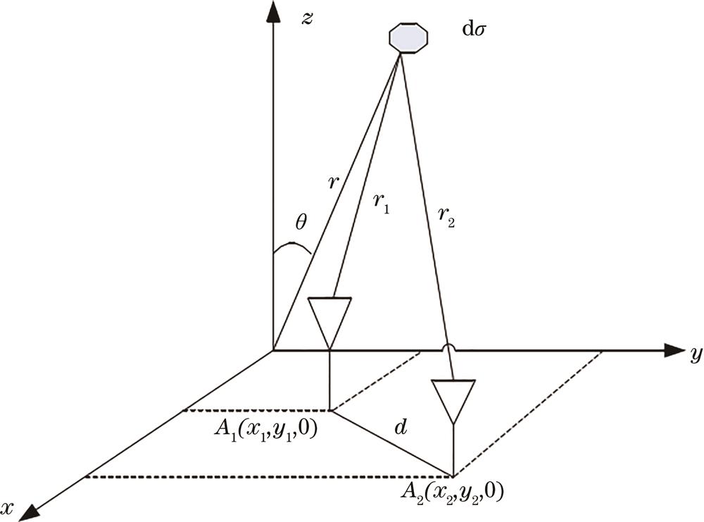
    Fig. 2. Detection principle schematic diagram of two receiving units
    Structure diagrams of space-based telescope schematic. (a) Folding form; (b) unfolding form
    Fig. 3. Structure diagrams of space-based telescope schematic. (a) Folding form; (b) unfolding form
    Structure layout of synthetic aperture telescope. (a) Layout of synthetic aperture telescope; (b) forming receiving sampling points in UV domain
    Fig. 4. Structure layout of synthetic aperture telescope. (a) Layout of synthetic aperture telescope; (b) forming receiving sampling points in UV domain
    Submirror structure layout. (a) Schematic diagram of submirror detector channel layout; (b) receiving sampling points in UV domain formed by detectors spaced 1 mm apart
    Fig. 5. Submirror structure layout. (a) Schematic diagram of submirror detector channel layout; (b) receiving sampling points in UV domain formed by detectors spaced 1 mm apart
    Receiving sampling points in UV domain by array center misalignment
    Fig. 6. Receiving sampling points in UV domain by array center misalignment
    Synthetic aperture diffractive mirror
    Fig. 7. Synthetic aperture diffractive mirror
    Aperture traverse display when aperture is 0. 207 m, F number is 2. (a) Aperture traverse; (b) aperture traverse projection
    Fig. 8. Aperture traverse display when aperture is 0. 207 m, F number is 2. (a) Aperture traverse; (b) aperture traverse projection
    Aperture traverse projection after compensation when aperture is 0. 207 m, F number is 2
    Fig. 9. Aperture traverse projection after compensation when aperture is 0. 207 m, F number is 2
    Inverse imaging simulation results. (a) Initial brightness temperature diagram of point radiation source; (b) inversion of brightness temperature map by point radiation source, when minimum baseline of the submirror center is 0.207 m; (c) inversion of brightness temperature map by point radiation source, when minimum baseline of the submirror center is 1 mm by 3×3 array; (d) inversion of brightness temperature map by point radiation source, when minimum baseline of the submirror center is 1 mm by array center misalignment
    Fig. 10. Inverse imaging simulation results. (a) Initial brightness temperature diagram of point radiation source; (b) inversion of brightness temperature map by point radiation source, when minimum baseline of the submirror center is 0.207 m; (c) inversion of brightness temperature map by point radiation source, when minimum baseline of the submirror center is 1 mm by 3×3 array; (d) inversion of brightness temperature map by point radiation source, when minimum baseline of the submirror center is 1 mm by array center misalignment
    Daojing Li, Jiang Wu, Kai Zhou, Jinghan Gao, Anjing Cui. Space-Based Infrared Radio Telescope with 6.5 m Diffractive Synthetic Aperture[J]. Laser & Optoelectronics Progress, 2023, 60(10): 1011001
    Download Citation