
Qing'an Ding, Lijun Zhang, Junkai Li, Liuge Du, Li Zheng, Zhenfei Dai, Huixin Liu, Xudong Cheng, Chaofan Li. Research Progress of Converged Radio Over Fiber-Passive Optical Network System Based on Microwave Photonics[J]. Laser & Optoelectronics Progress, 2022, 59(23): 2300003
- Laser & Optoelectronics Progress
- Vol. 59, Issue 23, 2300003 (2022)
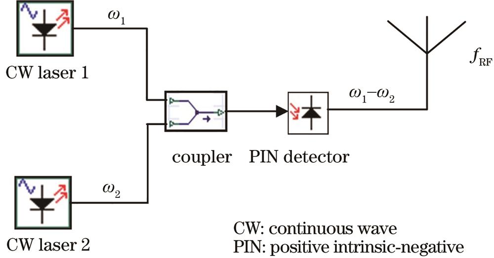
Fig. 1. Principle of optical heterodyne
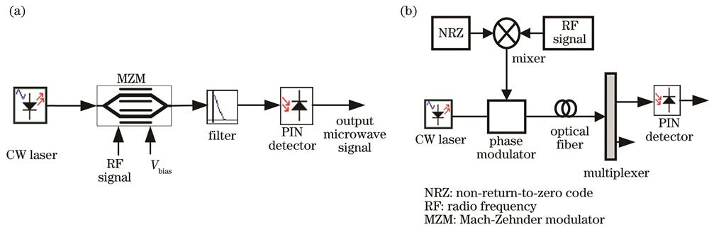
Fig. 2. Schematic diagram of millimeter wave generation. (a) Generated by intensity modulation; (b) generated by phase modulation
Fig. 3. Structure of RoF communication system
Fig. 4. Illustration of NG-PON2 architecture with TWDM-PON and PtP WDM-PON[25]
Fig. 5. Wavelength plan for NG-PON2[26]
Fig. 6. Structure of RoF-PON network
Fig. 7. Structure of RoF-WDM-PON system
Fig. 8. Downstream eye diagram of four-channel RoF-WDM-PON system for B2B transmission
Fig. 9. Downstream eye diagram of four-channel RoF-WDM-PON system for 20 km optical fiber transmission
Fig. 10. Upstream eye diagram of four-channel RoF-WDM-PON system for B2B transmission
Fig. 11. Upstream eye diagram of four-channel RoF-WDM-PON system for 20 km optical fiber transmission
Fig. 12. Structure of RoF-TWDM-PON system
Fig. 13. Downstream eye diagram of four-channel RoF-TWDM-PON system for B2B transmission
Fig. 14. Downstream eye diagram of four-channel RoF-TWDM-PON system for 20 km optical fiber transmission
Fig. 15. Upstream eye diagram of four-channel RoF-TWDM-PON system for B2B transmission
Fig. 16. Upstream eye diagram of four-channel RoF-TWDM-PON system for 20 km optical fiber transmission
Fig. 17. Structure of RoF-OFDM-WDM-PON system
Fig. 18. Structure of OFDM channel
Fig. 19. Downstream constellation diagram of four-channel RoF-OFDM-WDM-PON system for B2B transmission
Fig. 20. Downstream constellation diagram of four-channel RoF-OFDM-WDM-PON system for 50 km fiber transmission
Fig. 21. Upstream eye diagram of four-channel RoF-OFDM-WDM-PON system for B2B transmission
Fig. 22. Upstream eye diagram of four-channel RoF-OFDM-WDM-PON system for 50 km fiber transmission
Fig. 23. Downstream signal spectra of (a) RoF-WDM-PON, (b) RoF-TWDM-PON, and (c) RoF-OFDM-WDM-PON systems during downstream transmission
Fig. 24. Received results of downstream signal of each system as received optical power changes
Fig. 25. BER versus fiber length of downstream transmission in RoF-WDM-PON and RoF-TWDM-PON systems
Fig. 26. Q factor versus fiber length of upstream transmission in RoF-WDM-PON and RoF-TWDM-PON systems
Fig. 27. BER versus fiber length of upstream transmission in RoF-WDM-PON and RoF-TWDM-PON systems
|
Table 1. Comparison of three RoF-PON converged systems


Set citation alerts for the article
Please enter your email address

© Copyright 2018-2021 | Chinese Laser Press. All Rights Reserved 沪ICP备15018463号-20