
Shi-Tong Xu, Junxing Fan, Zhanqiang Xue, Tong Sun, Guoming Li, Jiandi Li, Dan Lu, Longqing Cong, "Active control of terahertz quasi-BIC and asymmetric transmission in a liquid-crystal-integrated metasurface," Photonics Res. 12, 2207 (2024)
- Photonics Research
- Vol. 12, Issue 10, 2207 (2024)

Fig. 1. (a) Schematic diagram of liquid crystal (LC)-integrated quasi-BIC metasurface. Here LC is filled into the cell between two graphite electrodes, and a static magnetic field pre-anchors LC molecules along the u
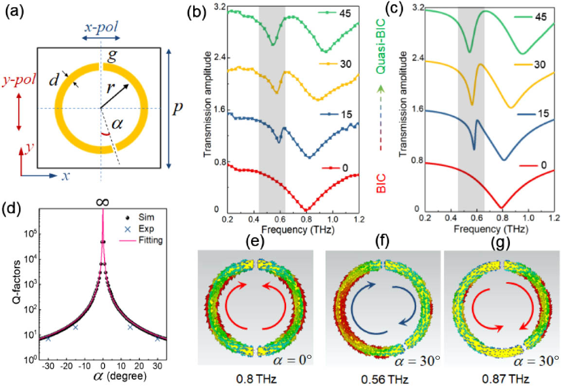
Fig. 2. (a) Schematic diagram of DSRR as a building block of a metasurface array. (b) Experimental and (c) simulated transmission amplitude spectra of DSRR with different rotation angles of 0°, 15°, 30°, and 45° under y Q α α = 0 ° α = 30 °
Fig. 3. (a) Schematic diagram of LC birefringence measurement under electric (z y y z α = 30 ° x y
Fig. 4. (a) Schematic diagram of measurement setup for LC-integrated metasurface. The first polarizer (P 1 x T x x T y x P 2 z u T x x T y x + z T x x T y x − z
Fig. 5. Analysis of asymmetric transmission of LC-integrated metasurface. Polarization conversion and transmittance spectra at (a) forward incidence and (b) backward incidence. Amplitude transmission (dB) at forward and backward incidence under the voltage of (c) 0 V, (d) 70 V, (e) 110 V, and (f) 150 V.
Fig. 6. Band diagram and radiative Q α = 0 °


Set citation alerts for the article
Please enter your email address

© Copyright 2018-2021 | Chinese Laser Press. All Rights Reserved 沪ICP备15018463号-20