• Laser & Optoelectronics Progress
  • Vol. 62, Issue 3, 0323001 (2025)
Yuwei Xu1,2,*, Zengzhou Yi1,2, Junkun Huang3, Wenyong Fu4, and Jingjin Zhang1,2
Author Affiliations
  • 1Key Laboratory of Optoelectronic Devices and Systems of Ministry of Education and Guangdong Province, Shenzhen 518060, Guangdong , China
  • 2College of Physics and Optoelectronic Engineering, Shenzhen University, Shenzhen 518060, Guangdong , China
  • 3North Night Vision Technology Co., Ltd, Kunming 650000, Yunnan , China
  • 4Nanyang Institute of Technology, Nanyang 473004, Henan , China
  • show less
    DOI: 10.3788/LOP241113 Cite this Article Set citation alerts
    Yuwei Xu, Zengzhou Yi, Junkun Huang, Wenyong Fu, Jingjin Zhang. Effects of Microchannel Plate Parameters on Performance of Image Intensifiers[J]. Laser & Optoelectronics Progress, 2025, 62(3): 0323001 Copy Citation Text show less
    MCP image enhancer. (a) MCP image enhancer structure modeled in CST; (b) section diagram of MCP; (c) front view of MCP input
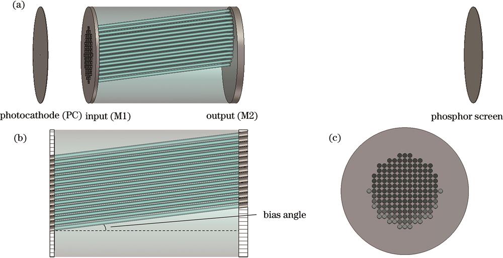
    Fig. 1. MCP image enhancer. (a) MCP image enhancer structure modeled in CST; (b) section diagram of MCP; (c) front view of MCP input
    Simulation of electron trajectory on microchannel board and distribution of electron landing points on phosphor screen
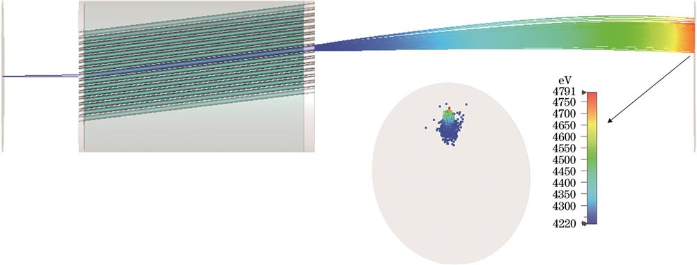
    Fig. 2. Simulation of electron trajectory on microchannel board and distribution of electron landing points on phosphor screen
    Results of different MCP working voltages. (a) MCP gain varies with the number of emitted electrons; (b) spatial resolution varies with the number of emitted electrons
    Fig. 3. Results of different MCP working voltages. (a) MCP gain varies with the number of emitted electrons; (b) spatial resolution varies with the number of emitted electrons
    Results of different bias angles. (a) Variation of MCP gain with working voltage; (b) spatial resolution variation with working voltage
    Fig. 4. Results of different bias angles. (a) Variation of MCP gain with working voltage; (b) spatial resolution variation with working voltage
    Results of different bias angles. (a) Variation of MCP gain with phosphor screen voltage; (b) spatial resolution variation with phosphor screen voltage
    Fig. 5. Results of different bias angles. (a) Variation of MCP gain with phosphor screen voltage; (b) spatial resolution variation with phosphor screen voltage
    Results of different phosphor screen voltages. (a) Variation of MCP gain with bias angle; (b) spatial resolution variation with bias angle
    Fig. 6. Results of different phosphor screen voltages. (a) Variation of MCP gain with bias angle; (b) spatial resolution variation with bias angle
    Variation of gain and spatial resolution with depth of output electrode
    Fig. 7. Variation of gain and spatial resolution with depth of output electrode