
Yunze Lei, Peng Gao, Xing Liu, Jiaoyue Li, Xiaofei Chen, Juanjuan Zheng, Sha An, Dan Dan, Baoli Yao. 3D Optical Sectioning Microscopy with Sparse Structured Illumination[J]. Laser & Optoelectronics Progress, 2023, 60(8): 0811016
- Laser & Optoelectronics Progress
- Vol. 60, Issue 8, 0811016 (2023)

Fig. 1. Schematic optical path of SSI-3DSM
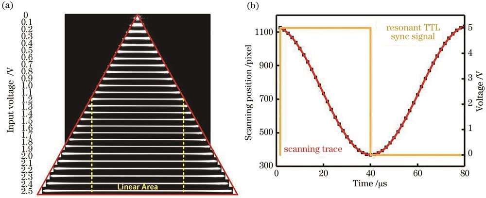
Fig. 2. Properties of the resonant scanning mirror. (a) The relationship between the scanning range of focus and different input voltages; (b) correspondence between focus position and scanning time
Fig. 3. Control principle of instrument signal. (a) Diagram of control signal timing; (b) the diagram of the control flow chart
Fig. 4. Background noise subtraction of SSI-3DSM
Fig. 5. Characterization of the period and phase shift of sparse stripe structured illumination. (a) Acquired image stack of sparse stripe structured illumination in different phase shift, the sample is a broad-band mirror (400-700 nm); (b) estimation of the period and phase for sparse stripe structured illumination in a image stack
Fig. 6. Axial resolution estimation of SSI-3DSM. (a) SSI-3DSM image stack of the fluorescent beads obtained from different axial planes; (b) axial resolution determination (FWHM) of SSI-3DSM; (c) axial resolution determination (FWHM) of 3D-scanning wide-field mode
Fig. 7. SBR estimation of scanning wide-field microscopy and SSI-3DSM. (a) Fluorescent images of fluorescent beads obtained with scanning wide-field (left) and SSI-3DSM (right) modes; (b) intensity profile along the dash-line in the inset ② crossing an individual bead from both the scanning wide-field and SSI-3DSM images; (c) SBR estimation of scanning wide-field and SSI-3DSM
Fig. 8. Comparison of OS-SIM and SSI-3DSM modes on optical sectioning capability. (a) Images of fluorescent beads in SSI-3DSM (top) and the scanning wide-field (bottom) images; (b) images of fluorescent beads in OS-SIM (top) and wide-field (bottom) modes; (c) signal-to-background ratio statistics for wide-field, OS-SIM, scanning wide-field, and SSI-3DSM modes
Fig. 9. SSI-3DSM imaging results of a metal step sample. (a) Comparison of the image qualities of the scanning wide-field and SSI-3DSM mode for a metal step sample; (b) three-dimensional optical sectioning image of a metal step sample,the different color represents the different height of the sample; (c) the height distribution along the dash-line in Fig.9 (b)


Set citation alerts for the article
Please enter your email address

© Copyright 2018-2021 | Chinese Laser Press. All Rights Reserved 沪ICP备15018463号-20