• Laser & Optoelectronics Progress
  • Vol. 60, Issue 17, 1712003 (2023)
Pengfei Li1,2, Dongsheng Zhai1,3, Zhulian Li1,3,*, and Yuqiang Li1,3
Author Affiliations
  • 1Yunnan Observatories, Chinese Academy of Sciences, Kunming 650216, Yunan, China
  • 2University of Chinese Academy of Sciences, Beijing 100049, China
  • 3Key Laboratory of Space Object & Debris Observation, Chinese Academy of Sciences, Nanjing 210023, Jiangsu , China
  • show less
    DOI: 10.3788/LOP222006 Cite this Article Set citation alerts
    Pengfei Li, Dongsheng Zhai, Zhulian Li, Yuqiang Li. Application Analysis of Tip/Tilt Mirror in 1.2 m Telescope Laser Ranging Receiving System[J]. Laser & Optoelectronics Progress, 2023, 60(17): 1712003 Copy Citation Text show less
    Optical path of 1.2 m telescope
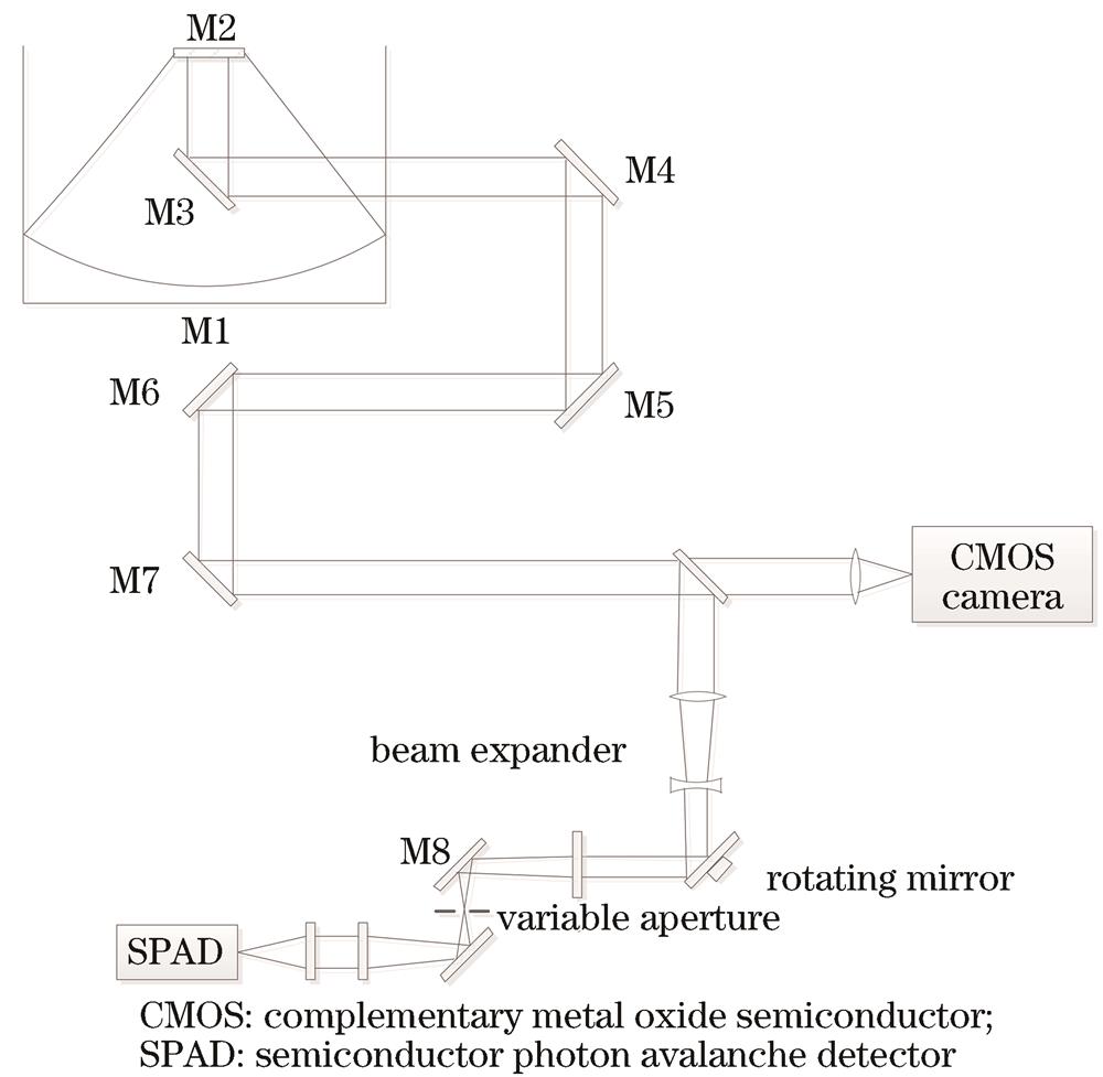
    Fig. 1. Optical path of 1.2 m telescope
    Background noise corresponding to different aperture diameters
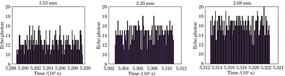
    Fig. 2. Background noise corresponding to different aperture diameters
    Relationship between maximum and minimum velocity aberrations and orbit height
    Fig. 3. Relationship between maximum and minimum velocity aberrations and orbit height
    Echo deviation measurement results. (a) Deviation measurement results; (b) variation of deviation with azimuth angle; (c) variation of deviation with altitude angle
    Fig. 4. Echo deviation measurement results. (a) Deviation measurement results; (b) variation of deviation with azimuth angle; (c) variation of deviation with altitude angle
    Simulation optical path diagram of receiving system
    Fig. 5. Simulation optical path diagram of receiving system
    Spot position with tip/tilt mirror at zero
    Fig. 6. Spot position with tip/tilt mirror at zero
    Aperture /mmField of view /(″)
    0.151.43
    1.009.50
    1.5014.20
    2.0019.00
    2.5023.80
    3.0028.50
    4.0038.00
    Table 1. Corresponding relationship between field aperture and field angle
    ParameterValue
    Spot size0.025
    Tip/tilt mirror diameter50
    Aperture diameter0.15-4.00
    Focusing lens focal length520
    Collimating lens focal length185
    Imaging objective focal length12
    Table 2. Optical path design parameters
    X direction angle of light source /(″)Y direction angle of light source /(″)Spot coordinateX direction angle of tip/tilt mirror /(″)Y direction angle of tip/tilt mirror /(″)Spot coordinate
    00(0.004,-0.003)00(0.004,-0.003)
    30(0.004,0.0203)62.550(0.003,-0.003)
    60(0.003,0.0408)125.100(0.004,-0.003)
    90(0.0003,0.0612)250.200(0.004,-0.002)
    03(0.0204,-0.004)062.55(0.003,-0.003)
    06(0.0408,-0.002)0125.10(0.003,-0.004)
    09(0.0611,-0.003)0250.20(0.004,-0.004)
    Table 3. Simulation results of tip/tilt mirror correcting echo direction
    Pengfei Li, Dongsheng Zhai, Zhulian Li, Yuqiang Li. Application Analysis of Tip/Tilt Mirror in 1.2 m Telescope Laser Ranging Receiving System[J]. Laser & Optoelectronics Progress, 2023, 60(17): 1712003
    Download Citation