• Acta Photonica Sinica
  • Vol. 52, Issue 2, 0212004 (2023)
Sanfeng HAO1,2, Jian ZHANG1,3,*, and Jianfeng YANG1
Author Affiliations
  • 1Xi'an Institute of Optics and Precision Mechanics,Chinese Academy of Science,Xi'an 710119,China
  • 2University of Chinese Academy of Sciences,Beijing 100049,China
  • 3Xidian University,School of Mechano-electronic Engineering,Xi'an 710071,China
  • show less
    DOI: 10.3788/gzxb20235202.0212004 Cite this Article
    Sanfeng HAO, Jian ZHANG, Jianfeng YANG. F/0.78 High Order Aspheric Surface Testing with Null Compensator and Mapping Distortion Correction[J]. Acta Photonica Sinica, 2023, 52(2): 0212004 Copy Citation Text show less
    Plot of the asphericity and asphericity slope
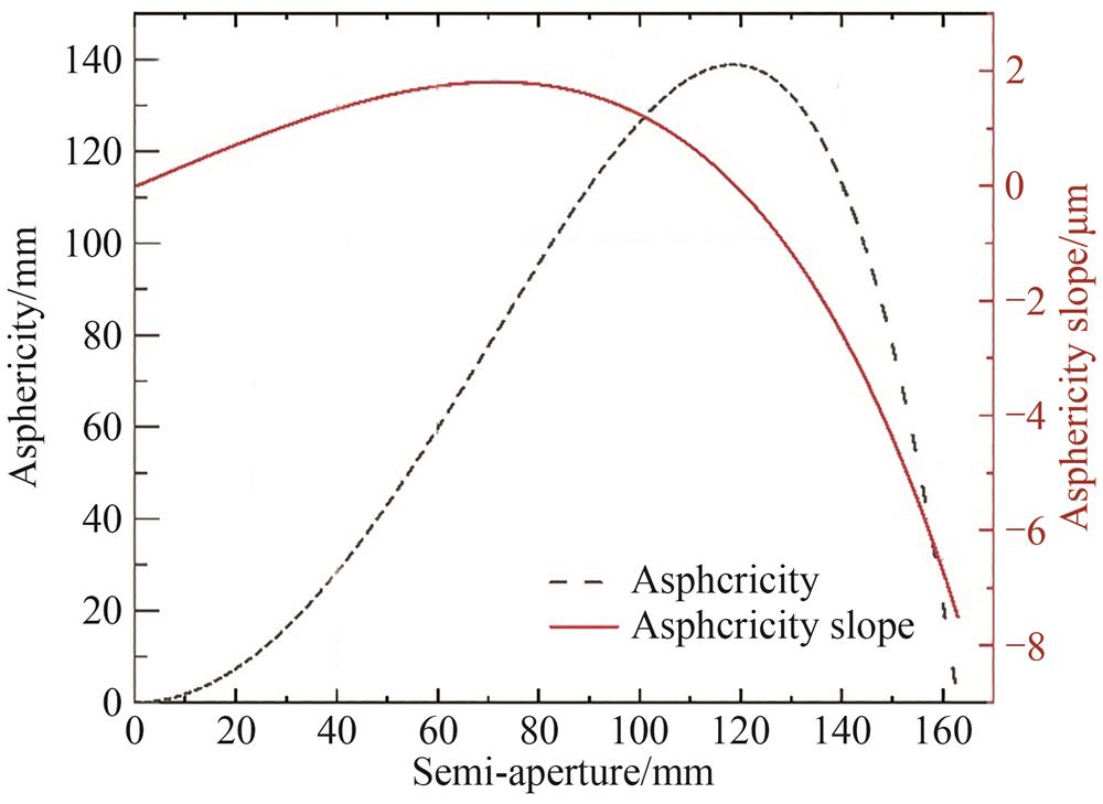
    Fig. 1. Plot of the asphericity and asphericity slope
    High order aspheric surface testing with three-piece lens null compensator
    Fig. 2. High order aspheric surface testing with three-piece lens null compensator
    The interactive interface of initial structural parameters calculation program
    Fig. 3. The interactive interface of initial structural parameters calculation program
    Optical layout with initial structure parameters
    Fig. 4. Optical layout with initial structure parameters
    The final design results of three-piece lens compensator
    Fig. 5. The final design results of three-piece lens compensator
    High-order aspheric surfaces testing with three-piece lens compensator
    Fig. 6. High-order aspheric surfaces testing with three-piece lens compensator
    High-order aspheric surface imaging with null lens compensator
    Fig. 7. High-order aspheric surface imaging with null lens compensator
    Schematic diagram of distortion principle
    Fig. 8. Schematic diagram of distortion principle
    Mapping distortion correction of interferometeric map
    Fig. 9. Mapping distortion correction of interferometeric map
    Optical deterministic polishing based on distortion correction map
    Fig. 10. Optical deterministic polishing based on distortion correction map
    ParametersValue
    Vertex curvature radius R/mm-491.14
    Conic constant K1.43
    4th coefficient A49.09×10-10
    6th coefficient A64.73×10-15
    8th coefficient A88.46×10-20
    Table 1. Parameters of high-order aspheric surface
    Surface No.Radius/mmThickness/mmMaterialSemi-diameters/mmFocal length/mm
    0Infinity59.89
    116.2255.65HK9L9.08-272.70
    212.82375.528.28
    3-106.668.16HK9L26.07-448.74
    4-203.20.5428.47
    558.089.00HK9L32.40-7450.73
    654.20396.1831.93
    Table 2. Structure data of null lens compensator
    ParameterUnitsDesign valueToleranceWavefront(RMS@632.8 nm)

    Reference surface irregularity

    of interferometer(RMS)

    λ0.0090.009
    Airspacemm59.890.013.92×10-7
    Lens 1:
    Radius 1Fringe16.22512.24×10-6
    Thicknessmm5.650.014.37×10-6
    Radius 2Fringe12.82312.97×10-6
    Surface 1 irregularity(RMS)λ1/801.29×10-2
    Surface 2 irregularity(RMS)λ1/801.29×10-2
    Index of refraction1.516 850.000 16.31×10⁻⁷
    Index inhomogeneity2×10-63×10-3
    Airspace 1mm75.520.017.22×10-7
    Lens 2:
    Radius 1Fringe-106.6611.43×10-6
    Thicknessmm8.160.012.31×10-7
    Radius 2Fringe-203.211.27×10-6
    Surface 1 irregularity(RMS)λ1/801.29×10-2
    Surface 2 irregularity(RMS)λ1/801.29×10-2
    Index of refraction1.516 850.000 11.3×10⁻⁶
    Index inhomogeneity2×10-64.5×10⁻³
    Airspace 2mm0.540.011.75×10-6
    Lens 3:
    Radius 1Fringe58.0812.83×10-8
    Thicknessmm90.013.69×10-6
    Radius 2Fringe54.213.44×10-7
    Surface 1 irregularity(RMS)λ1/801.29×10-2
    Surface 2 irregularity(RMS)λ1/801.29×10-2
    Index of refraction1.516 850.000 13.4×10⁻⁷
    Index inhomogeneity2×10-65×10-3
    Airspace 3mm396.180.028.44×10-8
    Residual Wavefrontλ0.001 2
    RSS0.017
    Table 3. Tolerances and error budget for null lens compensator
    ParametersTolerance
    Radius of curvature/ Fringe±1
    Surface irregularity(RMS)/λ1/80
    Lens thickness/mm±0.01
    Airspace/mm±0.01
    Index of refraction±0.000 1
    Index inhomogeneity2×10-6
    Decenter/mm±0.01
    Tilt/(°)±0.005
    Table 4. Tolerances of null lens compensator
    Surface No.Radius/mmF numberClear aperture diameter/mm
    116.2250.7564.0
    212.8230.7564.0
    3-106.661.582.0
    4-203.23.391.0
    558.081.582.0
    654.200.7564.0
    Table 5. Parameters of ZYGO transmission spheres for testing surface irregularity of null lens compensator
    Sanfeng HAO, Jian ZHANG, Jianfeng YANG. F/0.78 High Order Aspheric Surface Testing with Null Compensator and Mapping Distortion Correction[J]. Acta Photonica Sinica, 2023, 52(2): 0212004
    Download Citation