• Laser & Optoelectronics Progress
  • Vol. 59, Issue 23, 2306002 (2022)
Borui Yang1,2, Li Zhao2,*, and Ying Lu3
Author Affiliations
  • 1Nanjing Huadun Power Information Security Evaluation Co., Ltd., Nanjing 210000, Jiangsu , China
  • 2College of Information Science and Engineering, Xi'an Technological University, Xi'an 710003, Shaanxi , China
  • 3China Electronics Technology Group Tai Chi Xi'an R&D Center, Xi'an 710000, Shaanxi , China
  • show less
    DOI: 10.3788/LOP202259.2306002 Cite this Article Set citation alerts
    Borui Yang, Li Zhao, Ying Lu. PLC and VLC Cascade Communication System Based on CNDM-OFDM[J]. Laser & Optoelectronics Progress, 2022, 59(23): 2306002 Copy Citation Text show less
    Structure of the PLC-VLC cascade system based on CNDM-OFDM[8]
    Fig. 1. Structure of the PLC-VLC cascade system based on CNDM-OFDM[8]
    Geometric model of the indoor PLC-VLC system
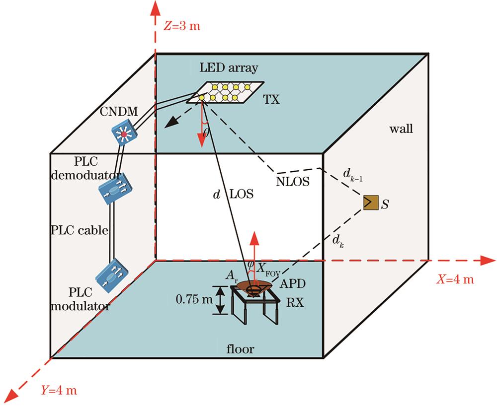
    Fig. 2. Geometric model of the indoor PLC-VLC system
    Cascade signal transmission model of PLC-VLC based on DCO-OFDM
    Fig. 3. Cascade signal transmission model of PLC-VLC based on DCO-OFDM
    Frame structure of multi-segment joint control signal
    Fig. 4. Frame structure of multi-segment joint control signal
    Training structure of the OFDM
    Fig. 5. Training structure of the OFDM
    Frequency response characteristics of PLC channel
    Fig. 6. Frequency response characteristics of PLC channel
    Frequency response characteristics of VLC channel
    Fig. 7. Frequency response characteristics of VLC channel
    Frequency response characteristics of PLC-VLC cascade channel
    Fig. 8. Frequency response characteristics of PLC-VLC cascade channel
    Evaluation of integrated characteristics of cascade systems. (a) Eye diagram and Q factor; (b) eye diagram and minimum BER
    Fig. 9. Evaluation of integrated characteristics of cascade systems. (a) Eye diagram and Q factor; (b) eye diagram and minimum BER
    OFDM performance of different modulation methods
    Fig. 10. OFDM performance of different modulation methods
    Experimental platform of the DCO-OFDM cascade communication
    Fig. 11. Experimental platform of the DCO-OFDM cascade communication
    Waveforms of off-line modulation and reception of cascaded systems. (a) Waveform obtained by off-line modulation at the transmitter; (b) waveform received by the cascaded system
    Fig. 12. Waveforms of off-line modulation and reception of cascaded systems. (a) Waveform obtained by off-line modulation at the transmitter; (b) waveform received by the cascaded system
    Constellation diagram of the received signal of the cascaded system
    Fig. 13. Constellation diagram of the received signal of the cascaded system
    ParameterValue
    Data subcarrier NSD48

    Pilot subcarrier NSP

    Total number of subcarriers NST

    4

    52=48+4

    Channel bandwidth /MHz20
    Subcarrier interval ΔF /MHz0.315
    IFFT/FFT period TFFT /μs3.2=1/ΔF
    GI duration TGI /μs0.8=TFFT/4
    Training sequence GI duration TGI2 /μs1.6=TFFT/2
    Preamble duration TPreamble /μs16=TShort+TLong
    Mark space TSYM /μs1.6=TFFT+TGI
    Short training sequence duration TShort /μs8=10TFFT/4
    Long training sequence duration TLong /μs8=TGI2+2TFFT
    Symbolic number of OFDM NSYM64
    Table 1. Frame parameters of multi-segment joint control signals
    kα0α1igidi /m
    1-2.1×10-38.11×10-1010.540200.0
    20.275221.0
    3-0.150242.0
    40.080259.0
    5-0.030266.0
    6-0.020530.0
    Table 2. Simulation parameters of PLC channel multipath attenuation (6-path)
    ParameterValue
    Room size /(m×m×m)4×4×3

    NLOS cutoff frequency /MHz

    Detector physical area of PD /m2

    8.5

    5×10⁻⁶

    Distance between LED and PD /m2.25
    FOV of a receiver PD /(°)60
    Radiation angle of emitter LED /(°)70
    Average reflectivity of the wall0.8
    LOS channel gain /dBm5.3×10-4
    NLOS channel gain /dBm1.3×10-4
    Table 3. Gain simulation parameters of VLC channel
    ParameterValue
    PLC-VLC system mapping modeQPSK/BPSK/16QAM

    PLC-VLC system modulation

    IFFT/FFT size

    FFT-OFDM

    64

    Number of effective subcarriers52
    Number of cyclic prefixes16
    DC bias coefficient /dB4
    Clipping factor /dB3
    Table 4. Parameters for the hierarchical simulation environment of the cascaded system
    ParameterValue
    LED luminous power /W1

    LED bandwidth /MHz

    APD effective photosensitive area φ /μm

    <5

    500

    APD spectral response range /nm400-1100
    Plano convex lens /mm80
    Blue filter /mm80
    Power line length /m5
    Transceiver distance /cm20
    Table 5. Parameters of the cascade system