• Chinese Optics Letters
  • Vol. 23, Issue 1, 010501 (2025)
Zhibiao Zhu, Yongfeng Li*, Zhe Qin, Lixin Jiang..., Wenjie Wang, Hongya Chen, Jiafu Wang, Lin Zheng and Shaobo Qu|Show fewer author(s)
Author Affiliations
  • Shaanxi Key Laboratory of Artificially-Structured Functional Materials and Devices, Air Force Engineering University, Xi’an 710051, China
  • show less
    DOI: 10.3788/COL202523.010501 Cite this Article Set citation alerts
    Zhibiao Zhu, Yongfeng Li, Zhe Qin, Lixin Jiang, Wenjie Wang, Hongya Chen, Jiafu Wang, Lin Zheng, Shaobo Qu, "Angular-adaptive spin-locked retroreflectors based on reconfigurable origami two-dimensional metagrating," Chin. Opt. Lett. 23, 010501 (2025) Copy Citation Text show less
    The proposed spin-locked retroreflector based on the Miura origami metagrating design. The origami metagrating is 2D. Therefore, the retroreflection can be achieved in both the x and y directions. When the origami metagratings are in different folding states, Px ≠ Py, θi,r1 ≠ θi,r2 ≠ θi,r3 ≠ θi,r4.
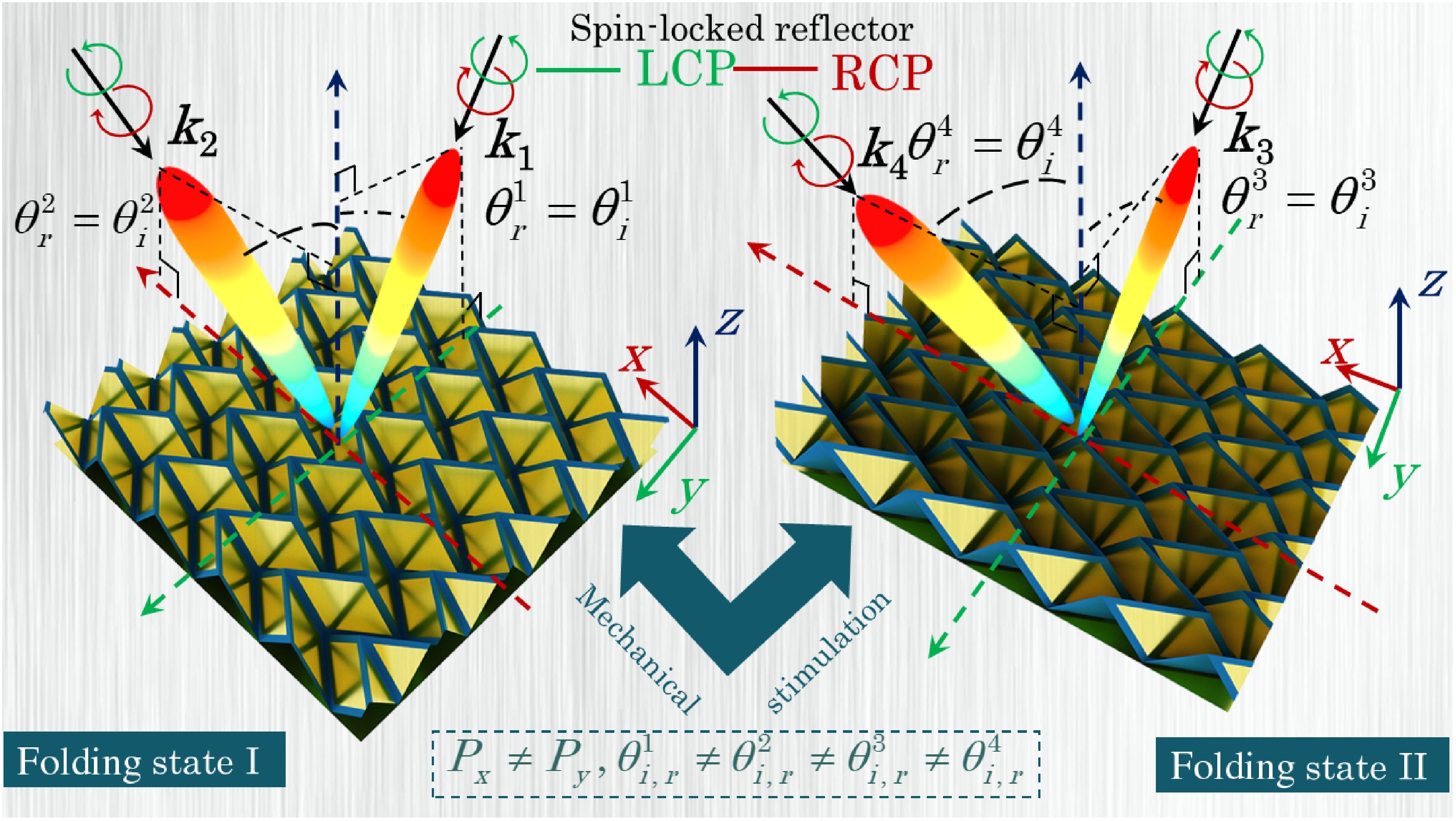
    Fig. 1. The proposed spin-locked retroreflector based on the Miura origami metagrating design. The origami metagrating is 2D. Therefore, the retroreflection can be achieved in both the x and y directions. When the origami metagratings are in different folding states, PxPy, θi,r1θi,r2θi,r3θi,r4.
    (a) Schematic representation of a general spin-locked metagrating with three Floquet modes under a TE-polarized incidence. It is worth mentioning that this principle also applies to a TM-polarized incidence. (b) Demonstration of induced electric current on the ground plane. (c) Schematic diagram of the folded Miura origami unit cell. The substrate of the Miura origami is a polyimide material, which is located on a perfect electrical conductor. The thickness of the substrate is only 0.075 mm, and the dielectric constant is εr = 3. (d) The distribution of creases. The period of the structure in the x-axis is Px, and the period in the y-axis is Py.
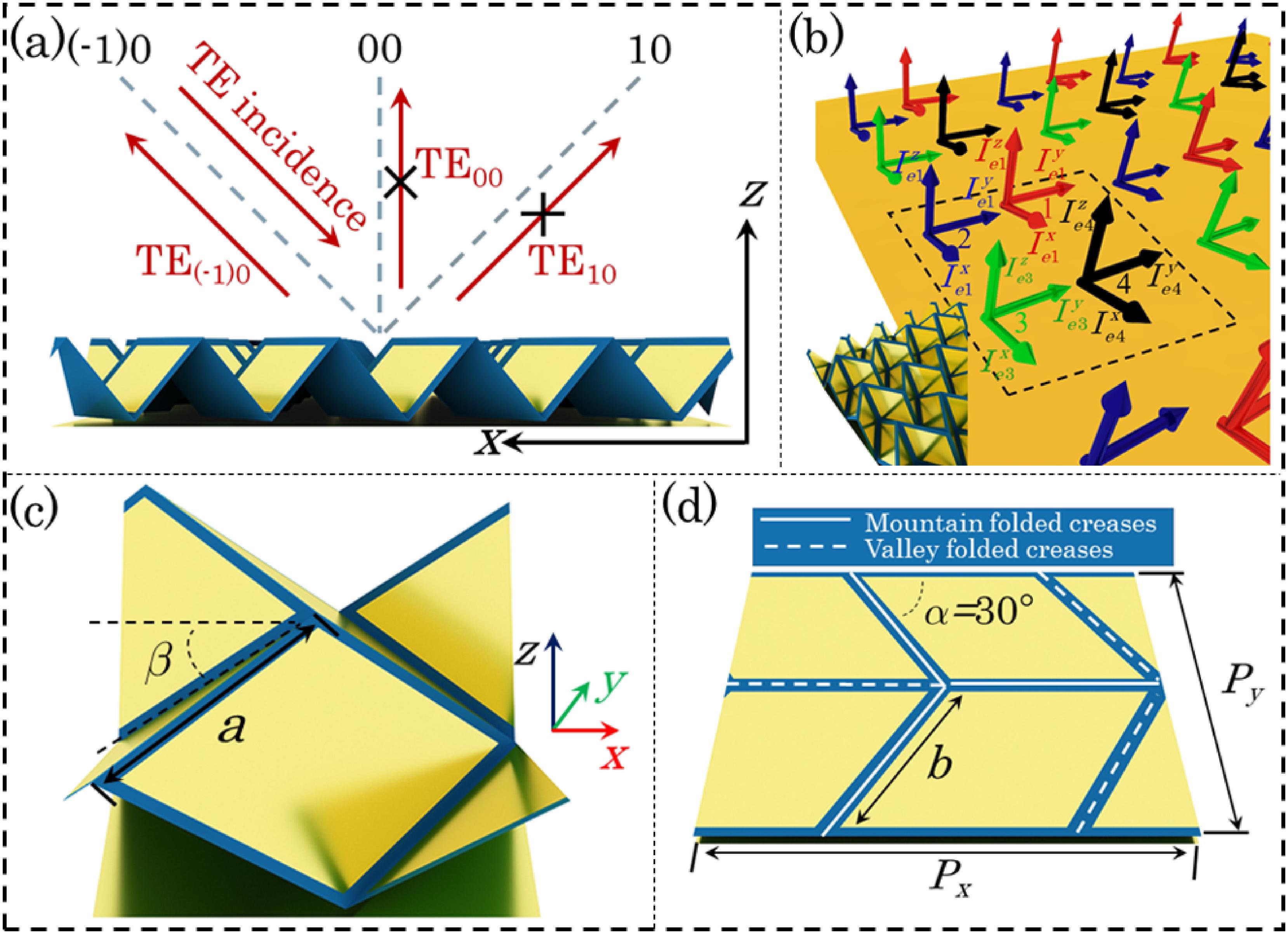
    Fig. 2. (a) Schematic representation of a general spin-locked metagrating with three Floquet modes under a TE-polarized incidence. It is worth mentioning that this principle also applies to a TM-polarized incidence. (b) Demonstration of induced electric current on the ground plane. (c) Schematic diagram of the folded Miura origami unit cell. The substrate of the Miura origami is a polyimide material, which is located on a perfect electrical conductor. The thickness of the substrate is only 0.075 mm, and the dielectric constant is εr = 3. (d) The distribution of creases. The period of the structure in the x-axis is Px, and the period in the y-axis is Py.
    Reflection coefficients and angles versus frequency for different Floquet modes under (a) the TE- and (b) the TM-polarized incidences. When the folding angle β of the retroreflector is tuned to 45°, the corresponding scattered electric field distribution of (c) the TE- and (d) the TM-polarized incidences on the zOx plane is obtained at θin = 36° illumination angle. (e) Schematic diagram of spin-locked retroreflection.
    Fig. 3. Reflection coefficients and angles versus frequency for different Floquet modes under (a) the TE- and (b) the TM-polarized incidences. When the folding angle β of the retroreflector is tuned to 45°, the corresponding scattered electric field distribution of (c) the TE- and (d) the TM-polarized incidences on the zOx plane is obtained at θin = 36° illumination angle. (e) Schematic diagram of spin-locked retroreflection.
    Simulation results of retroreflection amplitude and angle as a function of fold angle β under the TE- and TM-polarized incidences: (a) x-direction and (b) y-direction. The corresponding scattered electric field distribution of the TE- and TM-polarized incidences on the zOx plane: (c)–(d) θin = 34°, β = 40° and (e)–(f) θin = 42°, β = 50°. The corresponding scattered electric field distribution of the TE- and TM-polarized incidences on the zOy plane: (g)–(h) θin = 34°, β = 40° and (i)–(j) θin = 38°, β = 50°.
    Fig. 4. Simulation results of retroreflection amplitude and angle as a function of fold angle β under the TE- and TM-polarized incidences: (a) x-direction and (b) y-direction. The corresponding scattered electric field distribution of the TE- and TM-polarized incidences on the zOx plane: (c)–(d) θin = 34°, β = 40° and (e)–(f) θin = 42°, β = 50°. The corresponding scattered electric field distribution of the TE- and TM-polarized incidences on the zOy plane: (g)–(h) θin = 34°, β = 40° and (i)–(j) θin = 38°, β = 50°.
    Relationship between the scattering intensity and θ under TE- and TM-polarization incidences. x-direction: (a) β = 40°, |θref| = 34°, (b) β = 45°, |θref| = 36°, and (c) β = 50°, |θref| = 38°. y-direction: (d) β = 40°, |θref| = 34°, (e) β = 50°, |θref| = 42°, and (f) β = 60°, |θref| = 60°.
    Fig. 5. Relationship between the scattering intensity and θ under TE- and TM-polarization incidences. x-direction: (a) β = 40°, |θref| = 34°, (b) β = 45°, |θref| = 36°, and (c) β = 50°, |θref| = 38°. y-direction: (d) β = 40°, |θref| = 34°, (e) β = 50°, |θref| = 42°, and (f) β = 60°, |θref| = 60°.
    (a) The image shows the arch test platform. (b) Sample picture of the origami retroreflector.
    Fig. 6. (a) The image shows the arch test platform. (b) Sample picture of the origami retroreflector.
    When the wave vector is along the x-direction, experimental results of the scattered intensity distribution for retroreflection at various incidence angles of (a) 34°, (d) 36°, and (e) 38° under TE- and TM-polarized incidences. When the wave vector direction is along the y-direction, experimental results of the scattered intensity distribution for retroreflection at various incidence angles of (a) 34°, (d) 42°, and (e) 60° under TE- and TM-polarized incidences.
    Fig. 7. When the wave vector is along the x-direction, experimental results of the scattered intensity distribution for retroreflection at various incidence angles of (a) 34°, (d) 36°, and (e) 38° under TE- and TM-polarized incidences. When the wave vector direction is along the y-direction, experimental results of the scattered intensity distribution for retroreflection at various incidence angles of (a) 34°, (d) 42°, and (e) 60° under TE- and TM-polarized incidences.
    Zhibiao Zhu, Yongfeng Li, Zhe Qin, Lixin Jiang, Wenjie Wang, Hongya Chen, Jiafu Wang, Lin Zheng, Shaobo Qu, "Angular-adaptive spin-locked retroreflectors based on reconfigurable origami two-dimensional metagrating," Chin. Opt. Lett. 23, 010501 (2025)
    Download Citation