
Kai Chang, Shuo Wang, Yingjun Cheng, Zhipeng Tian, Rongsheng Lu, Xinglong Xie, Jingtao Dong. Dark Field Laser Scattering Surface Defect Detection Based on Point-to-Line Confocal Principle[J]. Laser & Optoelectronics Progress, 2025, 62(3): 0312007
- Laser & Optoelectronics Progress
- Vol. 62, Issue 3, 0312007 (2025)
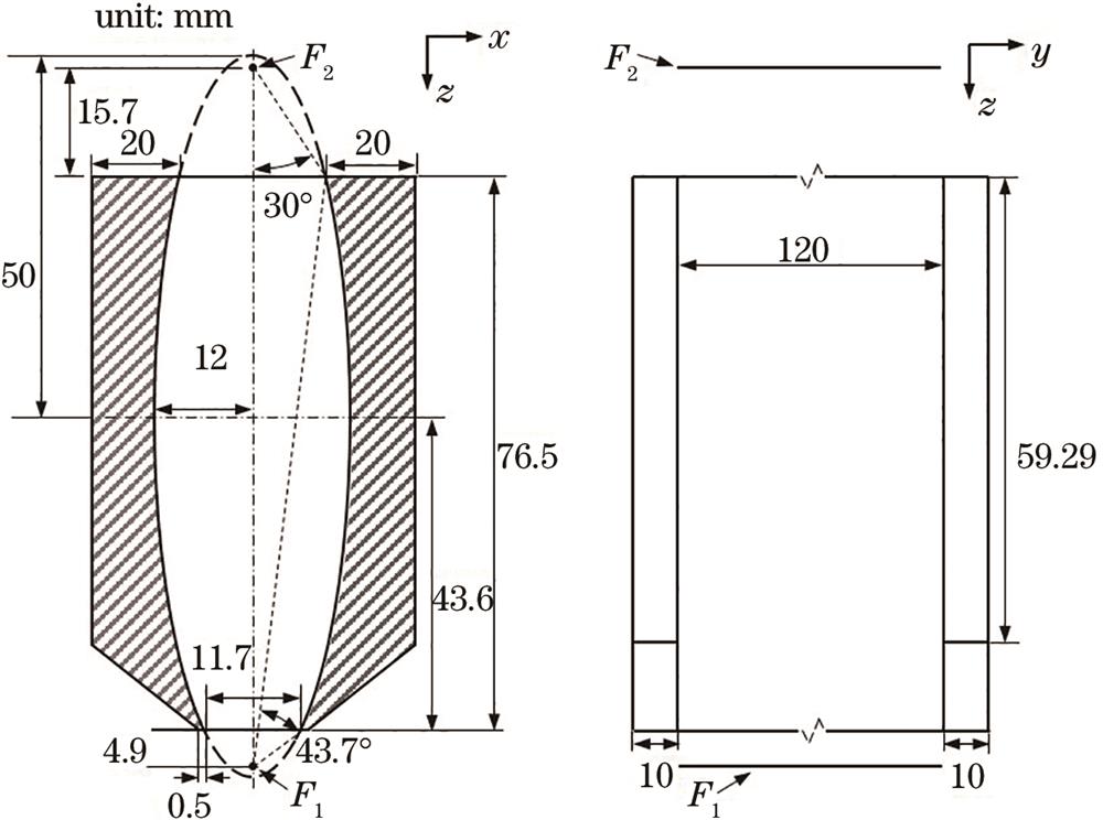
Fig. 1. Cross-section and side views of the columnar elliptical mirror in the x-z plane and the y-z plane, respectively
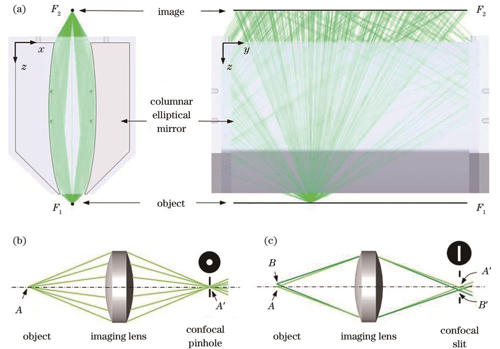
Fig. 2. Comparison of object-image conjugations among the columnar elliptical mirror, the point confocal system and the line confocal system. (a) Object-image relation of the columnar elliptical mirror; (b) object-image conjugation of the point confocal system; (c) object-image conjugation of the line confocal system
Fig. 3. Realization of the columnar elliptical mirror. (a) The columnar elliptical mirror and its internal profile measurement; (b) measurement results of the internal elliptical profiles
Fig. 4. Linear array optical fiber bundle and its entrance and exit
Fig. 5. The point-to-line confocal dark field laser scattering probe
Fig. 6. Analysis of scattered light collection efficiency. (a) Tracepro model; (b) normalized power curve of scattered light as a function of y coordinate along F1
Fig. 7. Analysis of the transverse optical sectioning ability. (a) (b) Tracepro models for scattering defect existing at the front surface and the back surface of a transparent sample; (c) normalized power curve of scattered light as a function of sample thickness
Fig. 8. Experimental system of surface defect detection. (a) 3D model; (b) prototype
Fig. 9. Strategy of high-speed laser line scan
Fig. 10. Diameter of the focal spot measured using knife edge method, the inset shows the uniformity of the spot diameter along F1
Fig. 11. Experimental results of the effective line field of view and the uniformity of scattering light collection. (a) Dark field scattering inspection of a steel rule surface; (b) normalized intensity curve of the scattering signal of the line indicated by the white arrows
Fig. 12. Experimental results of the transverse optical sectioning ability. (a) Experimental principle of transverse optical sectioning ability test using a wedge glass; (b)(c) dark-field scattering images of the front surface and the back surface; (d) signal-to-noise ratio of the probe for suppressing back-surface scattered light as a function of the wedge thickness
Fig. 13. Experimental results of the minimum detectable size. (a) SEM image of a fine scratch; (b) voltage signal of the scattered light of the fine scratch
Fig. 14. Dark field scattering inspection results of surface defects of a K9 glass plate with the aperture of 200 mm×200 mm and the thickness of 5 mm. (a) Full aperture image; (b) local detailed image


Set citation alerts for the article
Please enter your email address

© Copyright 2018-2021 | Chinese Laser Press. All Rights Reserved 沪ICP备15018463号-20