• Infrared and Laser Engineering
  • Vol. 51, Issue 7, 20210848 (2022)
Jinchi Yu, Yuan Hu, Binpeng Cheng, and Lei Zhang
Author Affiliations
  • School of Opto-electronic Engineering, Changchun University of Science and Technology, Changchun 130022, China
  • show less
    DOI: 10.3788/IRLA20210848 Cite this Article
    Jinchi Yu, Yuan Hu, Binpeng Cheng, Lei Zhang. Large field of view flat image plane splicing method for compound eye systems[J]. Infrared and Laser Engineering, 2022, 51(7): 20210848 Copy Citation Text show less
    Comparison of bionic compound eye. (a) Traditional curved compound eye; (b) Multifocal curved compound eye; (c) Flat-plane splicing compound eye
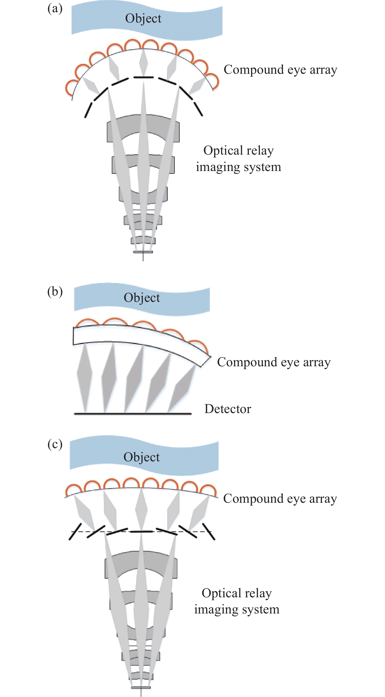
    Fig. 1. Comparison of bionic compound eye. (a) Traditional curved compound eye; (b) Multifocal curved compound eye; (c) Flat-plane splicing compound eye
    Flat-plane splicing
    Fig. 2. Flat-plane splicing
    Optical path difference under different number of eyes. (a) 13; (b) 11; (c) 9
    Fig. 3. Optical path difference under different number of eyes. (a) 13; (b) 11; (c) 9
    Maximum optical path difference, depth of field curve at different parameters. (a) Maximum optical path difference for differentn,; (b) Depth of field at differentf,D不同参数下的最大光程差、景深曲线。(a)不同n、对应的最大光程差;(b)不同f、D下的景深
    Fig. 4. Maximum optical path difference, depth of field curve at different parameters. (a) Maximum optical path difference for differentn, ; (b) Depth of field at differentf,D不同参数下的最大光程差、景深曲线。(a)不同n、对应的最大光程差;(b)不同f、D下的景深
    The corresponding relay D under different f, n, 不同f、n、下对应的中继口径D
    Fig. 5. The corresponding relay D under different f, n, 不同fn、 下对应的中继口径D
    Optical layout of the bionic compound eye imaging system
    Fig. 6. Optical layout of the bionic compound eye imaging system
    Simulation results for central ommatidium. (a) Field curvature and distortion; (b) Spot diagram; (c) MTF; (d) Wavefront
    Fig. 7. Simulation results for central ommatidium. (a) Field curvature and distortion; (b) Spot diagram; (c) MTF; (d) Wavefront
    Simulation results for the ommatidium at the extreme edge. (a) Curvature distortion; (b) Spot diagram; (c) MTF; (d) Wavefront
    Fig. 8. Simulation results for the ommatidium at the extreme edge. (a) Curvature distortion; (b) Spot diagram; (c) MTF; (d) Wavefront
    Design objectiveStandard requirement
    Acceptance angle of each ommatidium 2α/(°) 16
    Number of ommatidia n11
    Focal length of relay system/mm5
    Diameters of relay system D/mm 3
    Total FOV of the system $ \theta $/(°) 96
    Wavelength range λ/μm 0.4-0.9
    Focal length f/mm 0.5
    Table 1. Optical parameters of compound eye system with large field of view
    Jinchi Yu, Yuan Hu, Binpeng Cheng, Lei Zhang. Large field of view flat image plane splicing method for compound eye systems[J]. Infrared and Laser Engineering, 2022, 51(7): 20210848
    Download Citation