• Chinese Optics Letters
  • Vol. 23, Issue 2, 021204 (2025)
Tian Tian1, Min Li1, Yiwei Ma1,2,*, Song Li1..., Tao Geng1,** and Libo Yuan3|Show fewer author(s)
Author Affiliations
  • 1Key Laboratory of In-Fiber Integrated Optics, Ministry of Education, Harbin Engineering University, Harbin 150001, China
  • 2College of Materials Science and Chemical Engineering, Harbin Engineering University, Harbin 150001, China
  • 3Photonics Research Center, Guilin University of Electronics Technology, Guilin 541004, China
  • show less
    DOI: 10.3788/COL202523.021204 Cite this Article Set citation alerts
    Tian Tian, Min Li, Yiwei Ma, Song Li, Tao Geng, Libo Yuan, "Highly sensitive vector bending sensor based on chirped core fiber structure," Chin. Opt. Lett. 23, 021204 (2025) Copy Citation Text show less
    Schematic diagram of fiber bending. The surface over fiber axis and perpendicular to the bending direction is the neutral surface where x = 0. (s, θ) is the polar coordinate of the bending point.
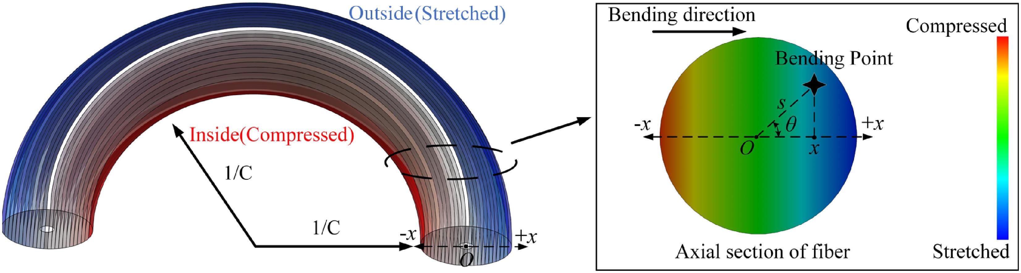
    Fig. 1. Schematic diagram of fiber bending. The surface over fiber axis and perpendicular to the bending direction is the neutral surface where x = 0. (s, θ) is the polar coordinate of the bending point.
    (a) Schematic diagram of the CC-MZI based on the SCF. (b) Light distributions on the vertical axis plane of the SCF for different values of the mis-core. (c) Comparison of the transmission spectra of Eq. (1) (l = 4.2 mm) and three samples of CC-MZIs.
    Fig. 2. (a) Schematic diagram of the CC-MZI based on the SCF. (b) Light distributions on the vertical axis plane of the SCF for different values of the mis-core. (c) Comparison of the transmission spectra of Eq. (1) (l = 4.2 mm) and three samples of CC-MZIs.
    (a) Fabrication steps of the CCS. (b) Real image of the CCS through a microscope. (c) Micrograph of the off-axis splicing between the SCF and the CCS.
    Fig. 3. (a) Fabrication steps of the CCS. (b) Real image of the CCS through a microscope. (c) Micrograph of the off-axis splicing between the SCF and the CCS.
    Schematic diagram of off-axis splicing using a fiber fusion splicer. (a) Fiber position distribution in the x–y plane. (b) Fiber position distribution in the x–z plane. (c) Structure observed from the y–z plane.
    Fig. 4. Schematic diagram of off-axis splicing using a fiber fusion splicer. (a) Fiber position distribution in the xy plane. (b) Fiber position distribution in the xz plane. (c) Structure observed from the yz plane.
    (a) Schematic diagram of the bending and temperature measurement platform. (b) Definition of bending direction.
    Fig. 5. (a) Schematic diagram of the bending and temperature measurement platform. (b) Definition of bending direction.
    (a) Variation of the broad spectrum with curvatures in the 0°, 90°, and 180° directions. (b) Spectral potential corresponding to the interference peak in the bending direction. The variation of transmission spectra with different curvatures at (c) 0°, (d) 90°, and (e) 180°.
    Fig. 6. (a) Variation of the broad spectrum with curvatures in the 0°, 90°, and 180° directions. (b) Spectral potential corresponding to the interference peak in the bending direction. The variation of transmission spectra with different curvatures at (c) 0°, (d) 90°, and (e) 180°.
    Fitting curves between the wavelength and the curvature at bending directions of 0°, 90°, and 180°. (a) Dip A. (b) Dip B. (c) Dip B–Dip A. (d) Fitted curve of the bending direction and curvature sensitivity of FSRA-B. (e) Error analysis.
    Fig. 7. Fitting curves between the wavelength and the curvature at bending directions of 0°, 90°, and 180°. (a) Dip A. (b) Dip B. (c) Dip B–Dip A. (d) Fitted curve of the bending direction and curvature sensitivity of FSRA-B. (e) Error analysis.
    Linear fitting curves for Dip A and Dip B. (a) Wavelength response to temperature. (b) Wavelength response to strain.
    Fig. 8. Linear fitting curves for Dip A and Dip B. (a) Wavelength response to temperature. (b) Wavelength response to strain.
    Fiber typeFiber numberCore/Cladding (μm)
    SMF110/125
    Few-mode fiber222/125
    MMF-1350/125
    MMF-24105/125
    No core fiber (NCF)50/125
    Table 1. Parameters of Fibers Used for Preparing CCS
    TypeMBS (nm/m−1)TCC (m−1/°C)NDDL (cm)
    S-TMF-S (MZI)[6]16.54.46 × 10−322
    S-M-SCF-M-S (MZI)[8]25.961.81 × 10−311.13
    HCF-S (FP and AR)[15]0.23457.33 × 10-210.12
    S-HCBG-S (ARROW)[16]0.07442.26 × 10-110.6
    S-bitaper-M-ball (MI)[17]−0.681.13 × 10−212.4
    PMF-LPFGs[18]9.261.59 × 10−222.7
    V-groove fiber (SPR)[19]−5.98Not given23.7
    CC-MZI−2301.13 × 10−430.45
    Table 2. Comparing the Performance of Different Types of Fiber Optic Curvature Sensors
    Tian Tian, Min Li, Yiwei Ma, Song Li, Tao Geng, Libo Yuan, "Highly sensitive vector bending sensor based on chirped core fiber structure," Chin. Opt. Lett. 23, 021204 (2025)
    Download Citation