• Optics and Precision Engineering
  • Vol. 32, Issue 17, 2663 (2024)
Jiawen WANG1, Junqing WU2, Minyang WU1, Yingbiao AN1..., Jingjing LIU2, Bin YAN2,* and Fujun YANG1,*|Show fewer author(s)
Author Affiliations
  • 1School of Civil Engineering, Southeast University, Nanjing289, China
  • 2Department of Orthodontics, The Affiliated Stomatological Hospital of Nanjing Medical University, Nanjing1009, China
  • show less
    DOI: 10.37188/OPE.20243217.2663 Cite this Article
    Jiawen WANG, Junqing WU, Minyang WU, Yingbiao AN, Jingjing LIU, Bin YAN, Fujun YANG. Whole-field deformation measurement of clear orthodontic aligner using electronic speckle pattern interferometry[J]. Optics and Precision Engineering, 2024, 32(17): 2663 Copy Citation Text show less
    Optical arrangement for speckle interference deformation measurement
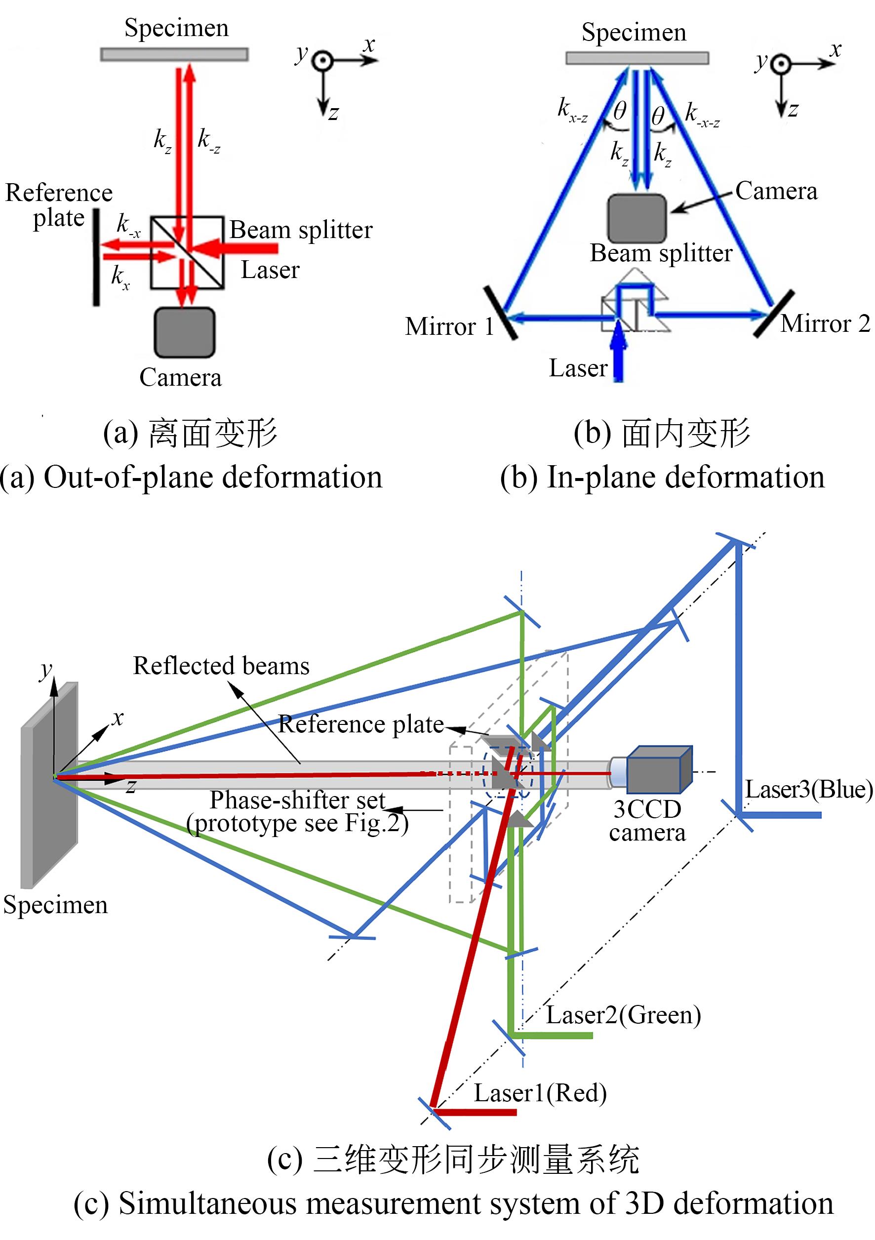
    Fig. 1. Optical arrangement for speckle interference deformation measurement
    Illustration of phase-shifter for tri-color
    Fig. 2. Illustration of phase-shifter for tri-color
    Schematic of phase shift generating for tri-color beams
    Fig. 3. Schematic of phase shift generating for tri-color beams
    Specimen production
    Fig. 4. Specimen production
    Experimental setup
    Fig. 5. Experimental setup
    Wrapped phase maps of u and v components
    Fig. 6. Wrapped phase maps of u and v components
    Phase distribution of same cross-section on phase maps and linear fitting results of unwrapped phase
    Fig. 7. Phase distribution of same cross-section on phase maps and linear fitting results of unwrapped phase
    Experimental setup for measuring 3D deformation of clear aligner
    Fig. 8. Experimental setup for measuring 3D deformation of clear aligner
    Color speckle pattern and its RGB components
    Fig. 9. Color speckle pattern and its RGB components
    Speckle fringe patterns of deformation components at initial stage
    Fig. 10. Speckle fringe patterns of deformation components at initial stage
    Wrapped phase related to speckle fringe patterns shown in Fig. 10
    Fig. 11. Wrapped phase related to speckle fringe patterns shown in Fig. 10
    Evolution of relative deformation every other 3 s of tested aligner in following 60 s
    Fig. 12. Evolution of relative deformation every other 3 s of tested aligner in following 60 s
    Phase maps related to 3D deformation components at 60 s after loaded u, v and w obtained by ESPI
    Fig. 13. Phase maps related to 3D deformation components at 60 s after loaded uv and w obtained by ESPI
    Denoised phase fringe patterns shown in Fig. 13 by window-deformable adaptive filter
    Fig. 14. Denoised phase fringe patterns shown in Fig. 13 by window-deformable adaptive filter
    Isoline distribution of derivatives obtained by digital differential operation on those unwrapped phase maps
    Fig. 15. Isoline distribution of derivatives obtained by digital differential operation on those unwrapped phase maps
    Three-dimensional distribution of clear aligner deflected deformation
    Fig. 16. Three-dimensional distribution of clear aligner deflected deformation
    Enhanced nephogram of strain component εxx
    Fig. 17. Enhanced nephogram of strain component εxx
    Driving stepMotor stepBased on uBased on v
    17.27.467.21
    214.414.4114.56
    321.621.7521.88
    428.828.9428.96
    536.035.7235.86
    643.243.0642.93
    750.450.3949.78
    Table 1. Rotational angles measured by proposed ESPI configuration
    Jiawen WANG, Junqing WU, Minyang WU, Yingbiao AN, Jingjing LIU, Bin YAN, Fujun YANG. Whole-field deformation measurement of clear orthodontic aligner using electronic speckle pattern interferometry[J]. Optics and Precision Engineering, 2024, 32(17): 2663
    Download Citation