
Tong Nan, Huan Zhao, Jinying Guo, Xinke Wang, Hao Tian, Yan Zhang. Generation of structured light beams with polarization variation along arbitrary spatial trajectories using tri-layer metasurfaces[J]. Opto-Electronic Science, 2024, 3(5): 230052
- Opto-Electronic Science
- Vol. 3, Issue 5, 230052 (2024)
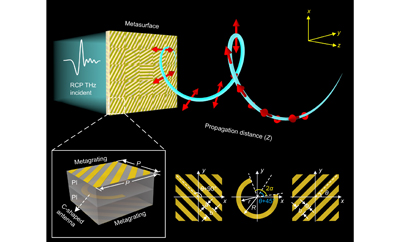
Fig. 1. Schematic diagram for generation of a structured light beam with polarization variation along arbitrary spatial trajectories using tri-layer metasurface.

Fig. 2. Schematic diagram of design concept for structured light beams. (a ) The phase distribution at the input plane. (b ) Spatial transmission trajectory of cylindrical helical path. (c ) Polarization distributions on the input plane. (d ) The polarization states corresponding to different propagation distances z on the Poincaré sphere for linear longitudinal polarization variations. (e ) Polarization distributions on the input plane. (f ) The polarization states corresponding to different propagation distances z on the Poincaré sphere for nonlinear longitudinal polarization variations.
Fig. 3. Schematic and characteristics of the designed unit cell. (a ) Concept of the designed tri-layer metasurface and the metallic structure of each layer. (b , c ) Microscope images of fabricated sample 1 and sample 2, respectively. The scale bar is 200 μm. (d ) Amplitude and phase modulation of the 128 selected antennas at 0.75 THz.
Fig. 4. Schematic of experimental setup. L, lens; PM, parabolic mirror; TP, THz polarizer; TQWP, THz quarter wave plate; BS, beam splitter; HWP, half-wave-plate; P, polarizer, QWP; quarter wave plate; WP, Wollaston prism; CCD: charge-coupled device.
Fig. 5. Experimental results for a structured light beam with linear longitudinal polarization variations along a helical transmission trajectory. (a , b ) Cross-sectional intensity profiles of the electric field at a propagation distance of z=15 mm for the simulation and experiment, respectively. (c ) Cross-sectional intensity profiles (red and blue solid lines) extracted from (a) and (b) at the locations of white dashed lines. (d ) The electric field component intensity and electric field intensity at different distances. (e , f ) Amplitudes and phase difference of electric field components Ex and Ey at different propagation distances. (g ) Theoretical, simulated and experimental transmission trajectories.
Fig. 6. Experimental results of a structured light beam with nonlinear longitudinal polarization variations along a helical transmission trajectory. (a ) Intensity distributions for Ex, Ey, and total electric field at different distances. (b ) Simulated and experimental amplitudes and (c ) phase difference of electric field components Ex and Ey at different propagation distances. (d ) Theoretical, simulated and experimental transmission trajectories.


Set citation alerts for the article
Please enter your email address

© Copyright 2018-2021 | Chinese Laser Press. All Rights Reserved 沪ICP备15018463号-20