
Donghai WANG, Wentao HOU, Na LI, Dongzhen LI, Xiaodong XU, Jun XU, Qingguo WANG, Huili TANG. Defects and Optical Property of Single-crystal Sapphire Fibers Grown by Edge-defined Film-fed Growth Method [J]. Journal of Inorganic Materials, 2020, 35(9): 1053
- Journal of Inorganic Materials
- Vol. 35, Issue 9, 1053 (2020)
Abstract
The single crystal fibers as a reinforcement for metal and ceramic matrix composites promise to serve in structural elements at temperatures in excess of 1500 ℃ in oxidizing conditions[
The following principal melt growth techniques have been successfully used to produce single-crystal oxide fibers: (1) edge-defined film-fed growth (EFG) method[
1 Materials and methods
1.1 Experimental
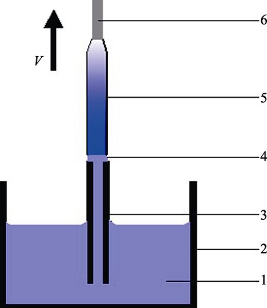
The sapphire fibers were grown by EFG method with a commercial Cz RF-heated system. Argon atmosphere was used as growth ambient with the pressure of 111- 122 kPa. A molybdenum crucible and die with central melt supply were used to grow single crystal fibers with diameter of 400-1000 µm and length of 25 cm. The raw material was placed in the molybdenum crucible. The fiber was pulled by an oriented crystal seed from the tip of the molybdenum die, as shown in Fig. 1.
![]()
Figure 1.Schematic experimental device1-Melt; 2-Crucible; 3-Die; 4-Meniscus; 5-Sapphire fiber; 6-Seed
The sapphire crystal was shaped with the sharp edge on the top of the die. Diameters of the grown fibers were slightly smaller than the diameter of the die.
The seeds with crystallographic orientation [0001] and $[{11\bar{2}0}]$ (perpendicular to planes c and a, accordingly) were used to grow sapphire fibers. The growth rate was 15-60 mm/h. During the first growth operations, the fluctuation in the diameter and irregular shape, as shown in Fig. 2(a) were observed due to poor temperature stabilization.
The heat loss from the crucible and the hot zone must be compensated during the growth process, which is the main reason of nonuniform of the diameter. So, fibers (diameter 400-1000 µm, length 500 mm) with good quality and regular shape were grown successfully in the following growth operations by more heat supplied, as shown in Fig. 2(b).
![]()
Figure 2.View of as-grown sapphire in which fibers with irregular shape (a) and regular shape (b)
Three single-crystal fiber samples with length of 2 mm were cut at different locations of 20, 90 and 150 mm away from the seed, respectively.
1.2 Numerical simulation
It is well known that fluid flow plays an important role in the processes of heat transport and mass transport in crystal growth from the melt. In order to determine the trajectory of a possible gas bubble located in the melt meniscus, the incompressible Navier-Stokes equations were considered:
Where v is the velocity vector, p is the pressure, $\eta $ is the dynamical viscosity, ρ is the density. The boundary conditions on the various surfaces (denoted by Ωi) are indicated in the Fig. 3.
![]()
Figure 3.Schematic diagram of the boundary conditions used in the numerical simulation
The dimensionless governing equations with the mentioned boundary conditions (specified in the Fig. 3) have been solved using the CGSim software. The computations were made in the stationary cases: growing fiber with radius of 0.5 mm with pulling rate of 30 mm/h and meniscus height of 0.2 mm.
2 Results and discussions
2.1 Crystal growth and defects in crystals
The cross section of the fibers was roughly circular without noticeable faceting on the lateral surface of the fiber. The diameter variation was within 40 µm in the whole fiber. Facets appeared only on one side of the a-plane. The facet probability of the sapphire fiber grown along the a-axis was defined by anisotropy of the surface energy and melt temperature fluctuations. Temperature instability also could induce the non-uniform lateral or normal facet growth, which could lead to defects and surface roughness shown in Fig. 4 and Fig. 5.
![]()
Figure 4.Growth stripes in the crystal structure caused by slight vibrations above the die,
![]()
Figure 5.Cross section morphology and bubbles' distribution in the cross section of the sapphire fibers
Fig. 6 shows the principles of the capillary shaping for EFG fiber growth method. It can be seen that stable shaped single crystals with constant diameter will be grown if the growth angle φ (the angle between the meniscus and the growth axis) is constant (φo). As a material constant, the parameter φo was determined by the thermodynamic equilibrium condition at the three-phase interface line, which does not depend on the growth parameters like pulling velocity, diameter and meniscus height. The parameters φo of different crystals are given in Table 1.
![]()
Figure 6.Principles of capillary shaping for EFG fiber growth method
| Materials | Orientation | Ref. | |
|---|---|---|---|
| Si | [111] | 11 | [10] |
| YAG | [100] | 11 | [11] |
| Sapphire | [0001] | 17 | [12] |
| Sapphire | $[10\bar{1}0]$ | 35 | [12] |
Table 1.
Parameter φo for different crystals
Deviations of the actual growth angle φ from φo result from perturbations of the meniscus height and radius, which lead to non-stationary variations of the fiber radii in agreement with:
The relationship between meniscus shape and crystal radius is given by the equation[
The relationship of theoretical meniscus shapes Z(R) and different fiber radii Rc is shown in Fig. 7. For the actual fiber geometry, meniscus shapes with different fiber radii Rc values were calculated. The dashed line shows the possible positions of the meniscus. There is a certain range of meniscus height for successful growth of crystals. The increase of height will induce the separation between the growing crystal and the meniscus. The decrease of height will cause the local interaction between the growing crystal and the die surface, which will reduce the crystal quality. The meniscus height depends on the material properties of the melt, pulling rate and ambient temperature distribution. The stable meniscus height and regular crystal shape can be achieved when temperature gradient at growth interface area was invariable. However, it is not easy to establish such conditions during the entire crystallization process. In order to maintain a stable meniscus height, we have to use an automated control system with computer-controlled feedback program that simultaneously monitored and controlled the fiber diameter and the die temperature. At the same time the pulling rate was invariable.
![]()
Figure 7.Relationship between theoretical meniscus shapes
The characteristic defects in sapphire crystal were the so-called voids or bubbles, which could reduce the optical and mechanical quality of crystals. In this work, sapphire fibers were studied with an optical microscope with 50× magnification. It was shown that there were bubbles running along the fibers. Fig. 8 shows a 50× micrograph of the EFG sapphire fiber.
![]()
Figure 8.Bubbles’ distribution observed on the lateral periphery of the fiber
The size of micro bubbles was about 5-10 µm. The most bubbles were spherical and exist on the periphery of the fiber. The distribution behavior of micro-bubbles was fairly related to growth rate and impurity effects (constitutional super cooling). Their occurrence has been demonstrated to be related to the stability of the solid liquid interface[
Another defect of the fiber was the Mo inclusions. As shown in Fig. 4, a small amount of Mo inclusions were observed, which are re-crystallized from solution in the sapphire. The Mo is generally oxidized by dissociation of the melt. The oxide dissolves in the melt, and is reduced to yield metallic molybdenum. This mechanism would seem to be confirmed by the appearance of the Mo in the inclusions. However, other aspects play a role on the generation of Mo inclusions. Notably, the new dies would produce more Mo inclusions at the first several runs as shown in Fig. 9(a).
![]()
Figure 9.Decrease in total Mo inclusion length with die life (a) and Mo concentration as a function of time from a sapphire melt (b)
In Fig. 9(a), the total content of Mo decreased with the frequency use of the crucible and die. It is concluded that new setups with the rougher machining surface, which leads to easier dissolution of Mo and increases the “output” of Mo into the melt. The high initial content of Mo inclusions can be seen when the crucible and die were first used. Another possibility is due to the poor vacuum of the equipment which results in more content of molybdenum oxide. Other experiments have sought to establish the “time relationship” of Mo in sapphire fibers. The Mo concentration in the samples measured by ICP analysis and the results were in Fig. 9(b).
Mo seems to be produced in substantial amounts early in the usage of the setup, and then diminishes after several runs. The die and its surroundings are likely the coldest part of the setup. It is apparent from examining used die that significant amounts of Mo are precipitated out on the outer surfaces.
2.2 Bubbles distribution and numerical simulation result of the fluid flow in the meniscus
The flow field in the meniscus (fiber radius 0.5 mm) and the corresponding bubbles in the crystals were shown in Fig. 10.
![]()
Figure 10.Flow field in the meniscus (fiber radius 0.5 mm) and corresponding bubbles in the crystals
The available experimental data suggest that the micro- bubbles distribution depends on the fluid flow in the meniscus. The distribution of the bubbles in the periphery of the meniscus suggested that the vortex of the fluid flow drove the bubbles move to the atmosphere under the thermo-capillary convection. The positions of these regions depend on the geometry shape of the die[
2.3 Optical properties
The absorption spectrum of the EFG sapphire fiber was shown in Fig. 11. The measured attenuation coefficient of the EFG fiber with length of 76 cm was 9 dB/m at 633 nm. The crystal quality of grown crystals by EFG method was worse than the crystals grown by LHPG method[
![]()
Figure 11.Absorption spectrum of the EFG sapphire fiber
3 Conclusion
Single-crystal sapphire fibers (diameter (400-1000) µm, length 500 mm) were grown with the EFG method successfully. The cross section of the c-axis fibers was roughly circular. The defects such as micro-bubbles, inclusions and growth stripes were observed and analyzed. The distribution of the micro-bubbles was studied with optical microscopy. The influence of the growth conditions on the size and distribution of micro-bubbles in sapphire fibers has been studied by experimental and numerical simulation of the fluid flow in the meniscus. The defect analysis and optical characterization exhibited the imperfect single crystalline structure of fibers.
References
[2] A WILSON B, M PETRIE C, E BLUE T. High temperature effects on the light transmission through sapphire optical fiber. Journal of the American Ceramic Society, 101, 3452-3459(2018).
[4] N KURLOV V, O STRYUKOV D, A SHIKUNOVA I. Growth of sapphire and oxide eutectic fibers by the EFG technique. Journal of Physics: Conference Series, 673, 012017(2016).
[5] S BERA, D NIE C, G SOSKIND M. Growth and lasing of single crystal YAG fibers with different Ho3+ concentrations. Optical Materials, 75, 44-48(2018).
[6] K LEBBOU. Single crystals fiber technology design. Optical Materials, 63, 13-18(2017).
[7] N KURLOV V, T MILEIKO S, A KOLCHIN A. Growth of oxide fibers by the internal crystallization method. Crystallography Reports, 47, S53-S62(2002).
[8] N KURLOV V, M KIIKO V, A KOLCHIN A. Sapphire fibres grown by a modified internal crystallisation method. Journal of Crystal Growth, 204, 499-504(1999).
[9] J FITZGIBBON J, M COLLINS J. High-volume production of low-loss sapphire optical fibers by Saphikon EFG (edge-defined, film-fed growth) method. International Society for Optics and Photonics, 3262, 135-141(1998).
[11] P RUDOLPH, T FUKUDA. Fiber crystal growth from the melt. crystal research and technology. Journal of Experimental and Industrial Crystallography, 34, 3-40(1999).
[12] K KAMADA, R MURAKAMI, V KOCHURIKHIN V. Single crystal growth of submillimeter diameter sapphire tube by the micro- pulling down method. Journal of Crystal Growth, 492, 45-49(2018).
[13] V ZHDANOV A, A SATUNKIN G, A TATARCHENKO V. Cylindrical pores in a growing crystal. Journal of Crystal Growth, 49, 659-664(1980).
[14] A TATARCHENKO V, N YALOVETS T, A SATUNKIN G. Defects in shaped sapphire crystals. Journal of Crystal Growth, 50, 335-340(1980).
[15] O BUNOIU, I NICOARA, L SANTAILLER J. Fluid flow and solute segregation in EFG crystal growth process. Journal of Crystal Growth, 275, e799-e805(2005).


Set citation alerts for the article
Please enter your email address

© Copyright 2018-2021 | Chinese Laser Press. All Rights Reserved 沪ICP备15018463号-20