• Chinese Optics Letters
  • Vol. 22, Issue 8, 080502 (2024)
Zhichang Mo1,2,3, Yi Chen1, Xiangyu Zhu1, Zhouhao Zhang1,4..., Dawei Li1,2,3, Jianda Shao1,2,3,5, Yuanan Zhao1,2,3,* and Jianguo Wang1,2,3,**|Show fewer author(s)
Author Affiliations
  • 1Laboratory of Thin Film Optics, Shanghai Institute of Optics and Fine Mechanics, Chinese Academy of Sciences, Shanghai 201800, China
  • 2Center of Materials Science and Optoelectronics Engineering, University of Chinese Academy of Sciences, Beijing 100049, China
  • 3Key Laboratory of Materials for High Power Laser, Chinese Academy of Sciences, Shanghai 201800, China
  • 4Henan Key Laboratory of Infrared Materials & Spectrum Measures and Applications, School of Physics, Henan Normal University, Xinxiang 453007, China
  • 5Hangzhou Institute for Advanced Study, University of Chinese Academy of Sciences, Hangzhou 310024, China
  • show less
    DOI: 10.3788/COL202422.080502 Cite this Article Set citation alerts
    Zhichang Mo, Yi Chen, Xiangyu Zhu, Zhouhao Zhang, Dawei Li, Jianda Shao, Yuanan Zhao, Jianguo Wang, "Optical secret sharing by multi-step liquid crystal planar doublet panning and coupling," Chin. Opt. Lett. 22, 080502 (2024) Copy Citation Text show less

    Abstract

    The hologram, which is formed by phases coupled through cascade devices for secret information sharing, still carries a cracking risk. We propose a liquid crystal planar doublet as the information carrier, and new holograms generated by the new coupled phases when the relative displacements of the different liquid crystal layers change. The designed geometrical phases are generated by an optimized iterative restoration algorithm, and each holographic image formed by these phases is readable. This scheme achieves an increase in the capacity of the stored secret information and provides more misdirection, which is expected to have potential value in optical steganography and storage.

    1. Introduction

    The development of technology has made exchange of information easier but has also increased the risk of information leakage. Ensuring information security is important[1,2]. On the network platform, information is hidden or encrypted by encoding, random key generation, and other methods[3,4]. However, for certain archives and documents with important values, there is a possibility of being deciphered and attacked when using the online mode of delivery. By physically copying and encrypting the original message, and then adopting an offline mode of delivery, these risks can be well avoided[5,6]. Among them, optical information encryption technology[7-9] can reproduce the original information well and effectively encrypt the information, combined with lens imaging and other optical reading methods; the entire preparation and reading are offline. Various small devices, such as random phase diffusers and thin films[10,11], can serve as carriers for encrypted information, offering improved camouflage.

    In recent years, metasurface-based encryption of optical information has developed rapidly[12,13], including multiple fundamental dimensions of light such as amplitude[14], phase[15], polarization[16], wavelength[17], orbital angular momentum[18], and spin angular momentum[19], combined with the phase transition and other properties of materials[20-22] to produce complex functions in information steganography. Liquid crystals, particularly nematic types, are extensively utilized as dynamically tunable phase-delay mediums. When combined with metasurfaces, as detailed in Refs. [23,24], they facilitate diverse optical field modulations[25,26]. Their application in optical holography is primarily due to geometrical phase modulation[27,28]. By integrating the limited penetration depth of light in chiral liquid crystals and their intrinsic stimuli-responsive characteristics, Peng et al. proposed a tunable holographic encryption method in which wavelength, polarization, helicity of light, and reaction duration can be used as the customized keys[29]. Also based on chiral liquid crystals, Liu et al. induced a spin-decoupled geometric phase according to the principle of independent manipulation of opposite-handed self-assembled helices. Under external physical excitation, dynamic multiplexed holography was achieved[30]. Compared to metasurface-based holography, LC-based holography has the following advantages of fast and large-area fabrication, low loss, band spectral response, and compatibility with mature liquid crystal display (LCD) technology. According to the application requirement, we have the flexibility to choose the passive liquid crystal polymer film structure or active liquid crystal cell structure[31]. Although the resolution of liquid crystal devices is lower than that of metasurface devices, the phase unit size of liquid crystal devices can already reach about 200 nm and even smaller based on laser direct writing, plasmonic photopatterning, and other methods[32,33]. Recently, a “four-in-one” optical information steganography technique was proposed in the literature[34]. This holographic design, which is based on the geometrical phase of liquid crystals, can effectively form a new hologram by combining four different holograms in a single plane. However, from a practical application point of view, the splicing of four liquid crystal box structures is difficult to realize; therefore, the holograms are prepared on the same liquid crystal flat panel in this study. There is ultimately a limitation on the hiding ability of single-layer devices, and cryptographic information can be easily obtained by traversing the optical dimensions. Therefore, the group subsequently proposed cascaded liquid crystal flat panels[35,36] to decompose information, effectively solving the risk of information leakage. The multilayer liquid crystal flat panel acts as the key to the information, generated by holographic or polarization modulation with different holographic patterns and encryption modes, and has the advantages of low risk and simple preparation. Huang et al. used the metasurface cascade, combined with the periodic expansion of the structure, to achieve the generation of different coupled holograms by left-right or even rotational motion[37,38].

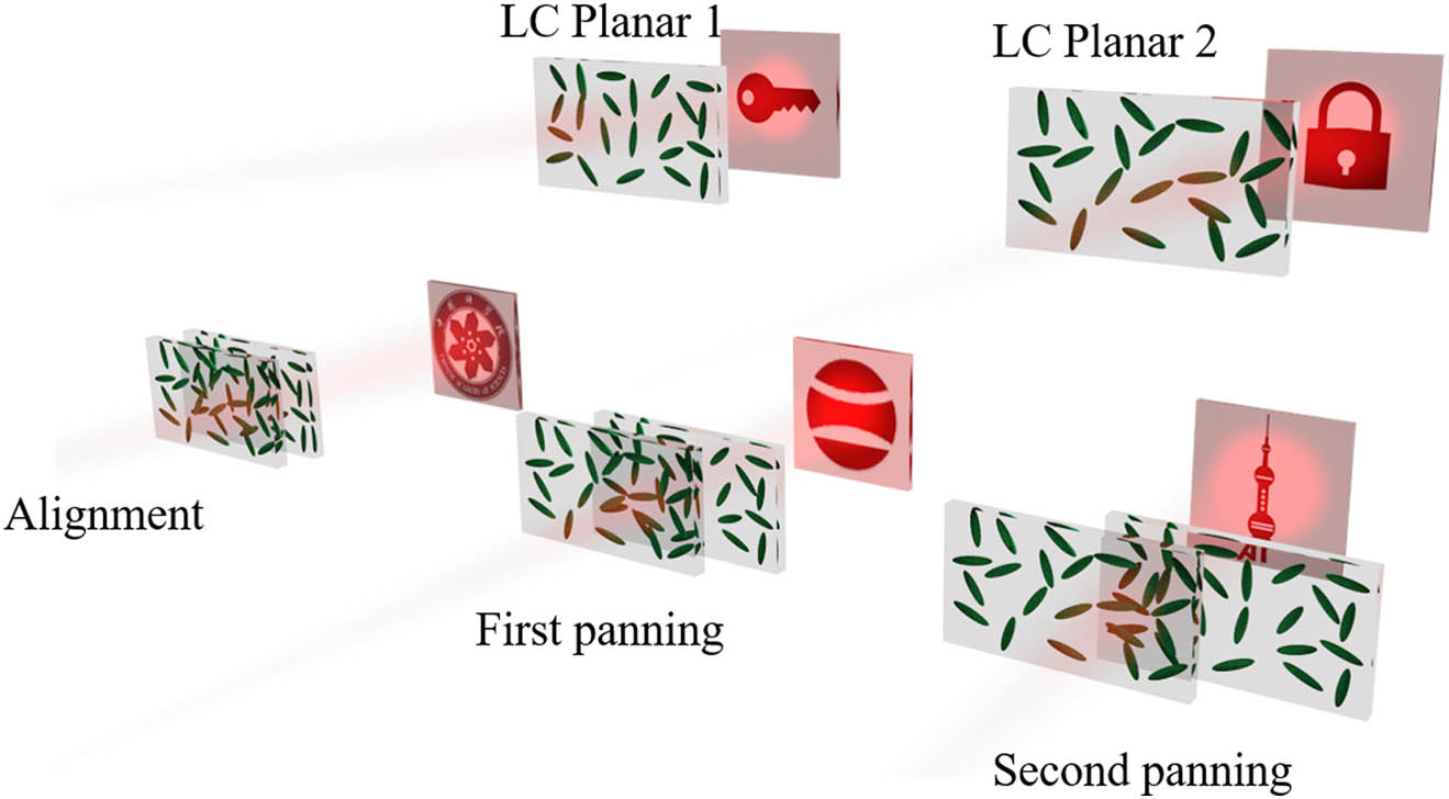
    Secret information can be observed through a simple alignment between cascaded devices, which still lack sufficient security. We propose optical information steganography based on a new coupling phase generated by multistep panning using a two-layer cascaded liquid-crystal flat panel, as shown in Fig. 1. Not only does each layer of the liquid crystal planar produce an erroneously induced holographic pattern through the geometric phase, but the coupled phase retains an erroneously induced pattern after the cascade is fully aligned. With the relative positions of the two layers of flat panels appearing staggered, only a part of the real pattern will appear, and with the displacement further moving to the corresponding position, the complete information will be displayed. This multi-step displacement for information steganography has high capacity and covertness. In this scheme, we used the gradient descent-based angular spectral method[35,39] to generate holograms and a single-step exposure technique[40] for geometric phase writing. The thickness of the liquid-crystal polymer film was designed in accordance with the half-wave condition at a 532 nm laser wavelength. The experimental and simulation results are in good agreement. Finally, we analyzed the impact of displacement misalignment to provide guidance for practical applications.

    Schematic of the different holographic displays based on the panning and coupling liquid crystal doublet structure.

    Figure 1.Schematic of the different holographic displays based on the panning and coupling liquid crystal doublet structure.

    2. Methods

    Liquid crystal materials have birefringent properties, so when polarized light is incident, the decomposed two perpendicular electric fields produce a phase difference, which can be defined as a phase delay δ=2πΔneffd/λ0. Here, Δneff is the effective birefringence index of the liquid crystal, d is the thickness of the liquid crystal layer, and λ0 is the wavelength of incident light. In liquid crystal polymer films, the thickness d can be adjusted, whereas conventional liquid crystal cells can have a voltage applied to adjust the effective refractive index Δneff[41]. In addition, for circularly polarized incident anisotropic liquid crystal molecules, a geometric phase is acquired, as shown in Fig. 2(a). The process can be described by the Jones matrix[42], that is, the incident circularly polarized light can be expressed as [ExinEyin]T=[1αi]T. Here, α=1 indicates that the incident light is left-handed circularly polarized, whereas α=1 means that the incident light is right-handed circularly polarized. After passing through the liquid crystal layer, the outgoing light matrix [ExoutEyout]T satisfies the following equation: [ExoutEyout]T=R(φ)T(δ)R(φ)[1αi]T.

    Schematic of the geometric phase generation and coupling process. (a) Single-pixel generation of the geometric phase. (b) Two aligned pixels generate multiple geometric phases. (c) New coupled phase distribution generations due to panning motion.

    Figure 2.Schematic of the geometric phase generation and coupling process. (a) Single-pixel generation of the geometric phase. (b) Two aligned pixels generate multiple geometric phases. (c) New coupled phase distribution generations due to panning motion.

    Here, R(φ)=[cosφsinφsinφcosφ] is the rotation matrix, and T=[eδ200eδ2] represents the phase retardation. The result can be written as [ExoutEyout]=12(cos  δ2[1αi]isin  δ2eiα·2φ[1αi]),where φ is the azimuthal angle of the liquid crystal molecule in the plane and 2φ is the geometrical phase obtained, whereas, for circularly polarized light incident on a dual-layer liquid crystal structure, the matrix can be expressed as [ExoutEyout]T=J2J1[1αi]T. Here, J2=R(φ2)T(δ2)R(φ2) and J1=R(φ1)T(1)R(φ1).

    For the [1αi]T output, the amplitude and phase items can be written as 12(icosδ12sinδ22eiα·2φ2+cosδ12cosδ22).

    Additionally, for the [1αi]T output, the amplitude and phase items can be written as 12(isinδ12cosδ22eiα·2φ1+sinδ12sinδ22eiα·2(φ1φ2)).

    Therefore, there will be three terms from Eqs. (2) and (3) with geometrical phase φ1, φ2, φ1φ2, and a background component as shown in Fig. 2(b). In addition, since the two thicknesses of the liquid crystal layers satisfy the half-wave condition with the phase delays of δ1=δ2=π, there exists only an amplitude factor sinδ12sinδ22=1, while the amplitude factors of the other phase terms are all 0, so the other phase terms and background component do not interfere the coupled phase φXYZφABC.

    φ1 and φ2 in Fig. 2(b) represent the pixel-to-pixel longitudinal alignment. φXYZ and φABC in Fig. 2(c) represent the pixel matrices of the longitudinal alignment on the spatial distribution. In other words, φXYZ=φ2(x,y), φABC=φ1(x,y), where x, y represent the spatial coordinates in the plane. Since the two-layer phase plates can be completely misaligned, φXYZ and φABC can be separately irradiated by the laser to generate their corresponding holograms. We divided each phase map into three regions, and from the matrix perspective, there are φABC=[φAφBφC] and φXYZ=[φXφYφZ]. We find that, with the first displacement of a plane, a new coupling phase appears after the relative position appears to change, and the coupled phase distribution can be written as φYZφAB. Similarly, φAB=[φAφB] and φYZ=[φYφZ]. After a further change in relative position, a newer coupled phase distribution φZφA appears. All these new coupled phase distributions can produce holographic patterns, changing only the number of pixel units involved in the diffraction. Thus, this new scheme can significantly expand the application scenarios of LC planar doublet.

    Design options for the phasors are discussed below. We ultimately require only the intensity patterns; therefore, there are multiple possible outcomes for the phase hologram. Using the target patterns under different displacement conditions as the criterion, we adjusted and optimized the phase recovery algorithm to ensure that the final result of the phase hologram reached convergence after each iteration. The phase-hologram design process is illustrated in Fig. 3.

    Flow charts of the iterative algorithm. (a) Single hologram generation process. (b) Generation flow for two-layer holograms and their coupled holograms. (c) Flow for outputting the final two holograms after introducing panning constraints.

    Figure 3.Flow charts of the iterative algorithm. (a) Single hologram generation process. (b) Generation flow for two-layer holograms and their coupled holograms. (c) Flow for outputting the final two holograms after introducing panning constraints.

    First, an accelerated iterative method for single hologram generation is illustrated in Fig. 3(a); we define this process as O1. Based on the angular spectral propagation theory, we set the distance of diffraction propagation of the phase hologram as z=10mm; then the propagation function H=exp(ikz1λfx2λfy2). Here, k=2π/λ is the wave number, and λ is the wavelength of incident light. fx and fy represent the spatial frequencies. A random phase distribution φ0 obtains its far-field intensity EA1 and phase distribution φA1 by one angular spectral operation. The FFT and iFFT denote the fast Fourier transform and inverse fast Fourier transform, respectively. The far-field intensity EA1 and the target light-field intensity ETarget are mixed as a set of scale factors a and b to produce a new field intensity EA1, which combines with φA1 to form the new light field. The new light field is propagated through the inverse angular spectrum operation, and a new hologram phase distribution input φA2 can be obtained. During the iteration process, this new phase distribution input can be appended with a gradient factor η to speed up the iteration process[35]. The correlation coefficient between the far-field pattern and the target pattern of the final output phase distribution was higher than a certain value, proving that the generation of this phase hologram was complete.

    The following must be achieved for both holograms and the coupled phase distribution between them to obtain their respective target far-field intensity distributions based on O1. We define this process as O2. As shown in Fig. 3(b), we can adjust the number of iterations and the scale factor in O1 to obtain the phase hologram φA and φZ. Then, the coupled phase distribution φL0=φZφA continues to use the O1 operation to obtain the new phase distribution φL1. Here, there exists a gradient as φL1φL0, which we introduce into the two intrinsic phase distributions and in conjunction with the scale factor c. This mixing process allows the two intrinsic phases to continue to maintain their coupling, equalizing the intrinsic phases and resulting in the two far-field images clearly appearing as one with the other one being very blurred.

    We next use the two phase holograms (φABC=[φAφBφC] and φXYZ=[φXφYφZ]) such that their respective far-field intensities are the target patterns I and II. The far-field pattern of the coupled phase distribution (φXYZφABC) is the target pattern III when they are cascaded and perfectly aligned.

    When the first displacement occurs, the far-field pattern of the coupled phase distribution (φYZφAB) is the target pattern IV; when the second displacement occurs, the far-field pattern of the coupled phase distribution (φZφA) is the target pattern V. As shown in Fig. 3(c), in the first step, random φABC0, φXYZ0 are taken as initial inputs and output φABC, φXYZ after O1, O2 operations. In the second step, parts φAB and φYZ of φABC and φXYZ are taken, and O2 operations are performed to output φAB1 and φYZ1. In the third step, parts φA1 and φZ1 of φAB1 and φYZ1 are taken, and O2 operations are performed to output φA2 and φZ2. Then, the outputs are populated back into the upper layer matrix and mixed with the set mixing coefficient factors m, n. The mixed results are then iterated back to the second step as input. In the fourth step, the output from this iteration is further populated back into the first step, with the mixing factors m, n set again, and overall, into a new round of iterations.

    Currently, there are several methods for pixelating the azimuthal angle of the liquid crystal molecules in a plane. We chose the single-step exposure method[40]. As shown in Fig. 4(a), in this method, the amount of phase delay of the pixels of the liquid crystal spatial light modulator (SLM) corresponds to the angle of polarization of the outgoing light. The photo orientation material (Lia-s, DIC, Japan) is sensitive to polarization, so the gray-scale image converted from the generated hologram is loaded into the SLM, which is then imaged onto the surface of the photo orientation thin film. Next, the birefringence parameter of the liquid crystal polymer (OCM-A1, Raitomaterials, China) is Δn=0.167 at 532 nm, so the thickness of the liquid crystal polymer film is chosen to be 1.59 µm according to the requirements of the half-wave conditions. After combination with the process parameter, we only need to spin-coat one layer of the polymer film to the surface of the photo alignment layer. When preparing the second layer again, the exposure pattern of the first layer can serve as a reference for determining the appropriate position coordinates for exposing another hologram image.

    (a) Exposure light path diagram. The laser passes through a beam expander and a polarizer and then irradiates the square aperture; the light field is imaged onto the SLM via lens 1 and lens 2. The image field is modulated by the SLM and quarter-wave plate (QWP), and then it is imaged onto the surface of the sample again by lens 3 and lens 4. The charge coupled device (CCD) receives the reflected light from the sample to observe the exposure process; two beam splitting (BS) prisms are used to change the direction of the light path. (b) Experimental sample pictures under orthogonal polarizers and without polarizers, respectively.

    Figure 4.(a) Exposure light path diagram. The laser passes through a beam expander and a polarizer and then irradiates the square aperture; the light field is imaged onto the SLM via lens 1 and lens 2. The image field is modulated by the SLM and quarter-wave plate (QWP), and then it is imaged onto the surface of the sample again by lens 3 and lens 4. The charge coupled device (CCD) receives the reflected light from the sample to observe the exposure process; two beam splitting (BS) prisms are used to change the direction of the light path. (b) Experimental sample pictures under orthogonal polarizers and without polarizers, respectively.

    The square aperture in Fig. 4(a) is imaged onto the sample surface by twice imaging, which facilitates positioning and alignment. The pixel size of the SLM is 8 µm, and the designed phase hologram size is 840×840 pixels.

    Figure 4(b) shows the final photograph of the double-layer sample. The liquid crystal polymer film exhibits a high contrast in the exposure area.

    3. Results and Discussion

    Figure 5(a) shows the optical path of the test. A laser beam with a wavelength of 532 nm was expanded and converted into circularly polarized light by passing through a line polarizer and a quarter-wave plate and then was irradiated onto the surface of the sample.

    (a) Holographic display optical path diagram. (b) Phase diagrams of the final output. (c) Simulation and experimental results of holographic images under different panning and coupling conditions.

    Figure 5.(a) Holographic display optical path diagram. (b) Phase diagrams of the final output. (c) Simulation and experimental results of holographic images under different panning and coupling conditions.

    The light wave was then diffracted to a plane at a set distance of z=10mm, and the light intensity distribution was observed using a camera. Figure 5(b) shows the final phase holograms.

    The results are shown in Fig. 5(c). By carefully tuning the parameters, all correlation coefficients of the simulated pattern were higher than 0.6. For target patterns I and II, the two independent holographic patterns are well reproduced with the text information “XYZ” and “ABC.” For target pattern III, the holographic pattern after fully aligned phase coupling also has a enough contrast, and the two English letters “OP” have a distinguishable outline shape. For the target pattern IV formed by secondly aligning the phase maps after panning, the sharpness of the two English letters “TI” is not very high in the experiment because of the mismatch between the pixels, which leads to a decrease in contrast. For target pattern V, in which the two English letters “CA” formed after further panning and sliding, the experimental result is sufficient. Overall, the experimental results and simulation results are relatively consistent, and the secret information “OPTICA” is well hidden. But the holographic pattern produced by the coupled phase distribution is not as clear as the holographic pattern produced by the single-layer phase distribution.

    Furthermore, the higher-order diffraction also formed the target pattern shape in the experiment, proving that our pattern formation originated from diffraction and not from the shape of the phase hologram. The beam spot needs to irradiate the hologram area as much as possible to make the pattern clearer, so the background spot position is usually in the middle of the diffracted image, and if the diffraction pattern is also designed in the middle of the hologram, it will result in a decrease in contrast. So we design the pattern at the edge of the hologram. Since the diffracted light will have much higher intensity relative to the background light, we can filter out the low intensity pixels by image processing by setting a gray-scale value. As shown in the Fig. 6(a), we can define the diffraction efficiency η=sum(Ipattern(i,j))sum(Ibeam(i,j)). Ipattern(i,j) represents the gray-scale value of each pixel of the designed information pattern after image processing. Ibeam(i,j) represents the gray-scale value of each pixel of the output beam spot. Thus, the diffraction efficiency is related to the gray threshold set during image processing, and we give a rough calculation as shown in Fig. 6(a). Here, the holographic pattern diffraction efficiencies produced by coupled phases are low due to the alignment error, phase writing error, parallelism of flat plate fitting during cascading, and selection of gray-scale thresholds. It should be noted that our phase writing relies on controlling the polarization state and imaging resolution of the exposure system. The phase accuracy of the SLM, the extinction ratio of the polarizer, and other factors influence the polarization state of the outgoing light, thereby impacting the phase accuracy. Second, our imaging area is 6.72mm×6.72mm, and it is difficult to ensure that the pixel shape is the same in all areas. It is likely that the pixel pattern will change from a regular square to an irregular spot, which also affects the final holographic display.

    (a) Holographic patterns after image processing. (b) Effect of the spot region on holograms. (c) Phase mismatch simulation result. (d) Contrast of no mixture and having a mixture process in the algorithm.

    Figure 6.(a) Holographic patterns after image processing. (b) Effect of the spot region on holograms. (c) Phase mismatch simulation result. (d) Contrast of no mixture and having a mixture process in the algorithm.

    In the actual test light path, we used a beam expander to adjust the spot size to get the best far-field intensity distribution. Of course, if the spot size is not adjustable, then spot irradiation of the uncoupled region does affect the coupled region, as shown in Fig. 6(b). When the spot area is smaller than the set hologram area, the far-field pattern will be blurrier than when the spot area and hologram area are the same. When the light spot region includes both coupled and uncoupled regions, the larger the proportion occupied by the uncoupled region, the blurrier the final pattern will be.

    The perfect alignment process is difficult on a small pixel scale. As shown in Fig. 6(c), the far-field pattern distribution of the two holograms here is “ABC” and “XYZ,” respectively, and the far-field pattern of their coupled phase distribution is two Chinese characters. So under the 8 µm pixel size condition, the mismatch of the layers will lead to the coupled phase being unable to restructure the clear image, and when the error σ exceeds 7 µm, the pattern is no longer recognizable. However, we believe that a high-precision alignment can be achieved by building a special imaging optical path for observation, even though this alignment technique is a mature technology in advanced semiconductor processes.

    Algorithmically, our scheme is further improved compared with that in the literature[35] on cascaded liquid crystals. We optimized the traditional phase recovery algorithm and introduced a phase mixture, which makes all the generated patterns possess sufficient error coefficients through different levels of iterations, as shown in Fig. 6(d). Although one of the images has decreased in sharpness, the other two have both improved to some degree. At the same time, this displacement is different from that in the literature[37], where a hologram is periodically expanded toward the outside and the dimensions of the two metasurfaces do not coincide. In contrast, we find a suitable solution directly for the interior using an algorithm that translates different distances to produce different patterns; thus, these two design ideas are different. It should be noted that there is a limit to the number of displacements, and too many target images entering the iterative process lead to unavoidable crosstalk. This is because the number of pixels is finite, and more target images indicate that the optimal solution must be found under more constraints, which is likely to lead to the non-convergence of the results. As shown in Fig. 7, all the parameters are precisely tuned to ensure that the correlation coefficients of the patterns generated by the coupled phases are above 0.6, and if the parameters in one of the iterations in the O3 step are changed, the final correlation coefficients will undergo a serious degradation. The new displacement process adds a new iterative process, so the changes in the correlation coefficients of all the patterns make it difficult to predict, and the complexity of the algorithm is greatly increased. However, reducing the pixel size, increasing the target image size, and combining algorithms such as deep learning are expected to improve the redundancy of holographic multiplexing, which can increase the number of displacement steps and encoding in the x, y directions. This method is potentially valuable in the field of multichannel messaging.

    Effect of changing the parameters of the algorithm iterations on the pattern correlation coefficients.

    Figure 7.Effect of changing the parameters of the algorithm iterations on the pattern correlation coefficients.

    This panning structure is mechanically easy to implement. For optical data storage[43] or multilayer diffractive neural networks[44], expanding this doublet configuration to multiple layers would allow for modularity and fast switching of functionality. There may be potential applications in vector light field regulation, precision displacement measurement[45], etc. Moreover, sliding is only one mode of motion, and our design concept can also be applied to other displacement modes, such as rotation, which will provide more dimensions for light-field modulation.

    In our work, the structure is the liquid crystal polymer film. If the cascade alignment process is improved, we can also choose the conventional liquid crystal cell structure for cascading. The liquid crystal cell structure can control the amplitude factor and modulate the intensity of the different holograms by changing voltage, which enables the transmission of information to be more covert. Our work effectively expands the information storage capacity, which is expected to be applied in various watermarking and optical steganography fields, thereby providing effective guarantee for information security.

    References

    [1] R. J. Anderson, F. A. P. Petitcolas. On the limits of steganography. IEEE J. Sel. Areas Commun., 16, 474(1998).

    [2] .

    [3] X. Liao, Y. Yu, B. Li et al. A new payload partition strategy in color image steganography. IEEE Trans. Circ. Syst. Video Tech., 30, 685(2020).

    [4] J. Tan, X. Liao, J. Liu et al. Channel attention image steganography with generative adversarial networks. IEEE Trans. Netw. Sci. Eng., 9, 888(2022).

    [5] W. Chen, B. Javidi, X. Chen. Advances in optical security systems. Adv. Opt. Photonics, 6, 120(2014).

    [6] X. Fan, Y. Zhu, N. Li et al. Acoustic metaholograms for encrypted information transmission. Phys. Rev. Appl., 20, 044048(2023).

    [7] G. Qu, W. Yang, Q. Song et al. Reprogrammable meta-hologram for optical encryption. Nat. Commun., 11, 5484(2020).

    [8] J. Guo, Y. Zhang, H. Ye et al. Spatially structured-mode multiplexing holography for high-capacity security encryption. ACS Photonics, 10, 757(2023).

    [9] X. Liu, J. Wu, W. He et al. Vulnerability to ciphertext-only attack of optical encryption scheme based on double random phase encoding. Opt. Express, 23, 18955(2015).

    [10] P. Rosenbaum, H. Barhom, A. Inberg et al. Hidden imaging in thin polymer films with embedded fluorescent peptide nanodots. Opt. Express, 32, 4485(2024).

    [11] M. Singh, A. Kumar. Optical encryption and decryption using a sandwich random phase diffuser in the Fourier plane. Opt. Eng., 46, 085009(2007).

    [12] Z. Li, M. Premaratne, W. Zhu. Advanced encryption method realized by secret shared phase encoding scheme using a multi-wavelength metasurface. Nanophotonics, 9, 3687(2020).

    [13] P. Zheng, Q. Dai, Z. Li et al. Metasurface-based key for computational imaging encryption. Sci. Adv., 7, eabg0363(2021).

    [14] K. T. P. Lim, H. Liu, Y. Liu et al. Holographic colour prints for enhanced optical security by combined phase and amplitude control. Nat. Commun., 10, 25(2019).

    [15] N. Yu, P. Genevet, M. A. Kats et al. Light propagation with phase discontinuities: generalized laws of reflection and refraction. Science, 334, 333(2011).

    [16] J. Xu, Z. Yue, P. Lu et al. Wavelength and polarization dual-multiplexed imaging based on holographic metasurfaces. Chin. Opt. Lett., 21, 100501(2023).

    [17] B. Xiong, Y. Xu, J. Wang et al. Realizing colorful holographic mimicry by metasurfaces. Adv. Mater., 33, 2005864(2021).

    [18] H. Ren, X. Fang, J. Jang et al. Complex-amplitude metasurface-based orbital angular momentum holography in momentum space. Nat. Nanotechnol., 15, 948(2020).

    [19] H. Yang, P. He, K. Ou et al. Angular momentum holography via a minimalist metasurface for optical nested encryption. Light Sci. Appl., 12, 79(2023).

    [20] C. Choi, S.-E. Mun, J. Sung et al. Hybrid state engineering of phase-change metasurface for all-optical cryptography. Adv. Funct. Mater., 31, 2007210(2021).

    [21] S. Venkatesh, X. Lu, H. Saeidi et al. A high-speed programmable and scalable terahertz holographic metasurface based on tiled CMOS chips. Nat. Electron., 3, 785(2020).

    [22] H. Yang, K. Ou, H. Wan et al. Metasurface-empowered optical cryptography. Mater. Today, 67, 424(2023).

    [23] S. Zhang, Q. Wang, X. Gao et al. Two-level optical encryption platform via an electrically driven liquid-crystal-integrated tri-channel metasurface. Opt. Lett., 48, 4125(2023).

    [24] J. Xiong, H. Zhong, D. Cheng et al. Full degree-of-freedom polarization hologram by freeform exposure and inkjet printing. PhotoniX, 4, 35(2023).

    [25] M. Gao, J. Wang, W. Cai et al. Dynamic propagation of an Airy beam in metasurface-enabled gradiently-aligned liquid crystals. Nanophotonics, 12, 4205(2023).

    [26] Y. Jin, N. P. Spiller, C. He et al. Zwitterion-doped liquid crystal speckle reducers for immersive displays and vectorial imaging. Light Sci. Appl., 12, 242(2023).

    [27] C. Li, B. Yu, B. Zhao et al. Full control of structured light with liquid-crystal geometric phase. Infrared Laser Eng., 52, 20230396(2023).

    [28] X. Fu, J. Yang, J. Wang et al. Completely spin-decoupled geometric phase of a metasurface. Photonics Res., 11, 1162(2023).

    [29] P. Chen, Z. Shen, C. Xu et al. Simultaneous realization of dynamic and hybrid multiplexed holography via light-activated chiral superstructures. Laser Photonics Rev., 16, 2200011(2022).

    [30] S. Liu, L. Zhu, Y. Zhang et al. Bi-chiral nanostructures featuring dynamic optical rotatory dispersion for polychromatic light multiplexing. Adv. Mater., 35, 2301714(2023).

    [31] K. Chen, C. Xu, Z. Zhou et al. Multifunctional liquid crystal device for grayscale pattern display and holography with tunable spectral-response. Laser Photonics Rev., 16, 2100591(2022).

    [32] J. Kim, Y. Li, M. N. Miskiewicz et al. Fabrication of ideal geometric-phase holograms with arbitrary wavefronts. Optica, 2, 958(2015).

    [33] K. Gao, H. H. Cheng, A. K. Bhowmik et al. Thin-film Pancharatnam lens with low f-number and high quality. Opt. Express, 23, 26086(2015).

    [34] X. Huang, D. Zhu, Z. Zhou et al. Tiger Amulet inspired high-security holographic encryption via liquid crystals. Nanophotonics, 12, 1787(2023).

    [35] Z. Wang, H. Zhang, X. Liu et al. Cascaded liquid crystal holography for optical encryption. Chin. Opt. Lett., 21, 120003(2023).

    [36] K. Li, Y. Wang, D. Pi et al. Multi-dimensional multiplexing optical secret sharing framework with cascaded liquid crystal holograms. Opto-Electron. Adv., 7, 230121(2024).

    [37] P. Georgi, Q. Wei, B. Sain et al. Optical secret sharing with cascaded metasurface holography. Sci. Adv., 7, eabf9718(2021).

    [38] X. Zhang, T. Li, H. Zhou et al. Switchable diffraction pattern based on cascaded metasurfaces. Laser Photonics Rev., 18, 2300887(2024).

    [39] D. S. C. Biggs, M. Andrews. Acceleration of iterative image restoration algorithms. Appl. Opt., 36, 1766(1997).

    [40] Y. Li, Y. Liu, S. Li et al. Single-exposure fabrication of tunable Pancharatnam-Berry devices using a dye-doped liquid crystal. Opt. Express, 27, 9054(2019).

    [41] Y. Yang, A. Forbes, L. Cao. A review of liquid crystal spatial light modulators: devices and applications. Opto-Electron. Sci., 2, 230026(2023).

    [42] Z. Wang, F. Li, Q. Deng et al. Inverse-designed Jones matrix metasurfaces for high-performance meta-polarizers. Chin. Opt. Lett., 22, 023601(2024).

    [43] M. Zhao, J. Wen, Q. Hu et al. A 3D nanoscale optical disk memory with petabit capacity. Nature, 626, 772(2024).

    [44] X. Yang, M. S. S. Rahman, B. Bai et al. Complex-valued universal linear transformations and image encryption using spatially incoherent diffractive networks. Adv. Photon. Nexus, 3, 016010(2024).

    [45] H. Zang, Z. Zhang, Z. Huang et al. High-precision two-dimensional displacement metrology based on matrix metasurface. Sci. Adv., 10, eadk2265(2024).

    Zhichang Mo, Yi Chen, Xiangyu Zhu, Zhouhao Zhang, Dawei Li, Jianda Shao, Yuanan Zhao, Jianguo Wang, "Optical secret sharing by multi-step liquid crystal planar doublet panning and coupling," Chin. Opt. Lett. 22, 080502 (2024)
    Download Citation