
Zihao Yu, Lihao Wang, Yang Wang, Yichen Liu, Zhenyu Wu. Research Progress and Development Trend of Fast Steering Mirror for Satellite Laser Communication[J]. Laser & Optoelectronics Progress, 2023, 60(15): 1500003
- Laser & Optoelectronics Progress
- Vol. 60, Issue 15, 1500003 (2023)
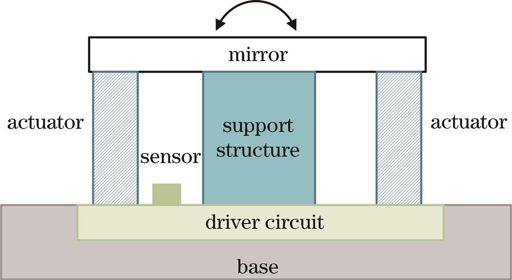
Fig. 1. Structure diagram of fast steering mirror (FSM)
![Structure diagram of high-bandwidth two-axis steering mirror (HBSM)[25]](/richHtml/lop/2023/60/15/1500003/img_02.jpg)
Fig. 2. Structure diagram of high-bandwidth two-axis steering mirror (HBSM)[25]
Fig. 3. Physical diagram of TNO FSM[26]
Fig. 4. Structure diagram of V-931.01[28]
Fig. 5. Structure diagram of simulation control FSM[29]
Fig. 6. PAM30 piezoelectric FSM's platform[30]
Fig. 7. S3 series piezoelectric pendulum[31]
Fig. 8. FSM structural model (left) and physical diagram (right) [32]
Fig. 9. FSM system model (left) and physical diagram (right) [33]
Fig. 11. Structure diagram of S34.T2S
Fig. 12. Structure diagram of A8L2.2[38]
Fig. 13. Laser communication systems of Stanford University (left) and Massachusetts Institute of Technology (right) [23]
Fig. 14. Structure diagram of S12237-03P[22]
Fig. 15. Laser communication system of LaSEINE lab[22]
Fig. 16. Photo of MEMS FSM test board (left) and scan curves in helix shape (right)
Fig. 17. Geometric relationship between FSM and beam when FSM rotates around a single axis
|
Table 1. Summary of FSMs' parameters


Set citation alerts for the article
Please enter your email address

© Copyright 2018-2021 | Chinese Laser Press. All Rights Reserved 沪ICP备15018463号-20