• Chinese Optics Letters
  • Vol. 23, Issue 3, 033701 (2025)
Xuan Yu1, Fei Yu2, Sheng Liu1, Cheng Lei1,*, and Du Wang1,**
Author Affiliations
  • 1The Institute of Technological Sciences, Wuhan University, Wuhan 430072, China
  • 2Shanghai Institute of Optics and Fine Mechanics, Chinese Academy of Sciences, Shanghai 201800, China
  • show less
    DOI: 10.3788/COL202523.033701 Cite this Article Set citation alerts
    Xuan Yu, Fei Yu, Sheng Liu, Cheng Lei, Du Wang, "Single dielectric layer terahertz tube fiber with negative curvature," Chin. Opt. Lett. 23, 033701 (2025) Copy Citation Text show less
    (a) TL as a function of tair with r = 4.5 and 4.34 mm for circular air core boundary and inverted circular air core boundary in the three-interface model, respectively. The common parameters are set as thickness t = 0.194 mm and refractive index n = 1.531. (b) Differential values of TL over tair with different absorption coefficients and structures.
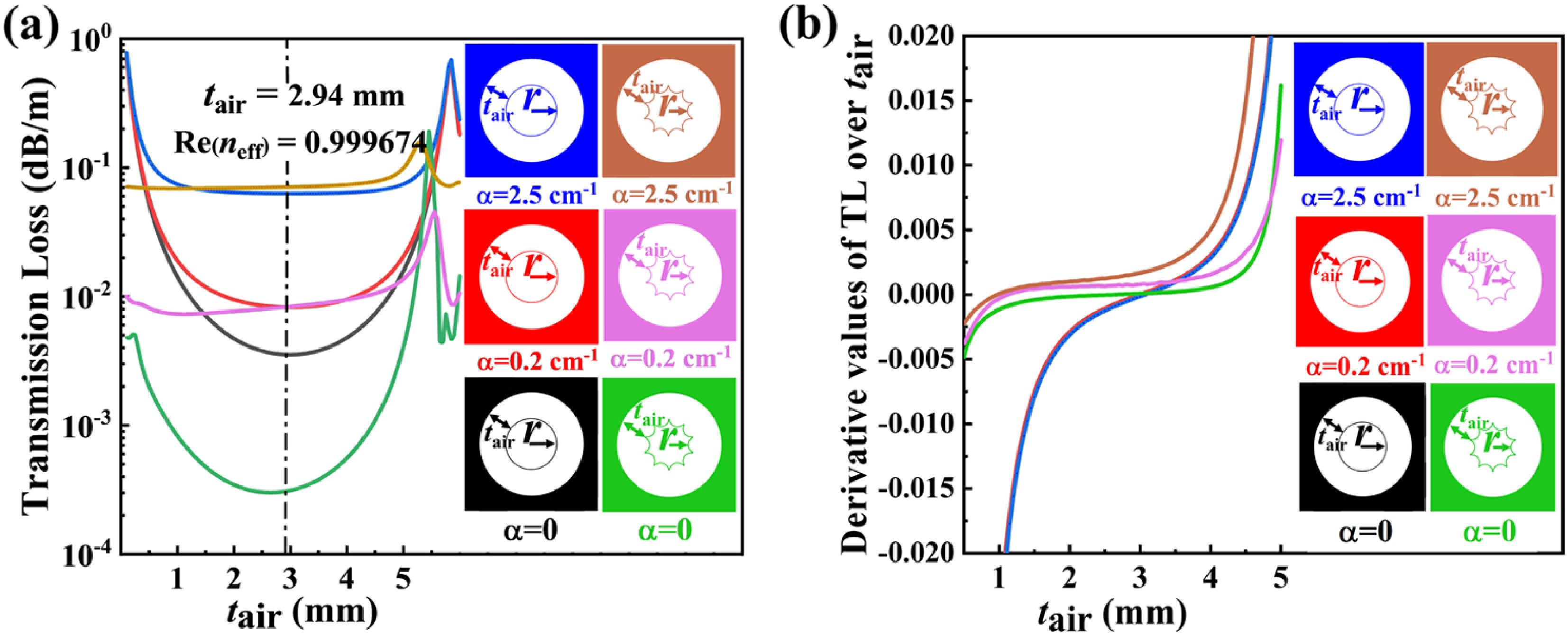
    Fig. 1. (a) TL as a function of tair with r = 4.5 and 4.34 mm for circular air core boundary and inverted circular air core boundary in the three-interface model, respectively. The common parameters are set as thickness t = 0.194 mm and refractive index n = 1.531. (b) Differential values of TL over tair with different absorption coefficients and structures.
    Fiber scheme and related parameters of the proposed THz NC-TF, where the air regions are white and the fiber material (TOPAS) regions are shaded.
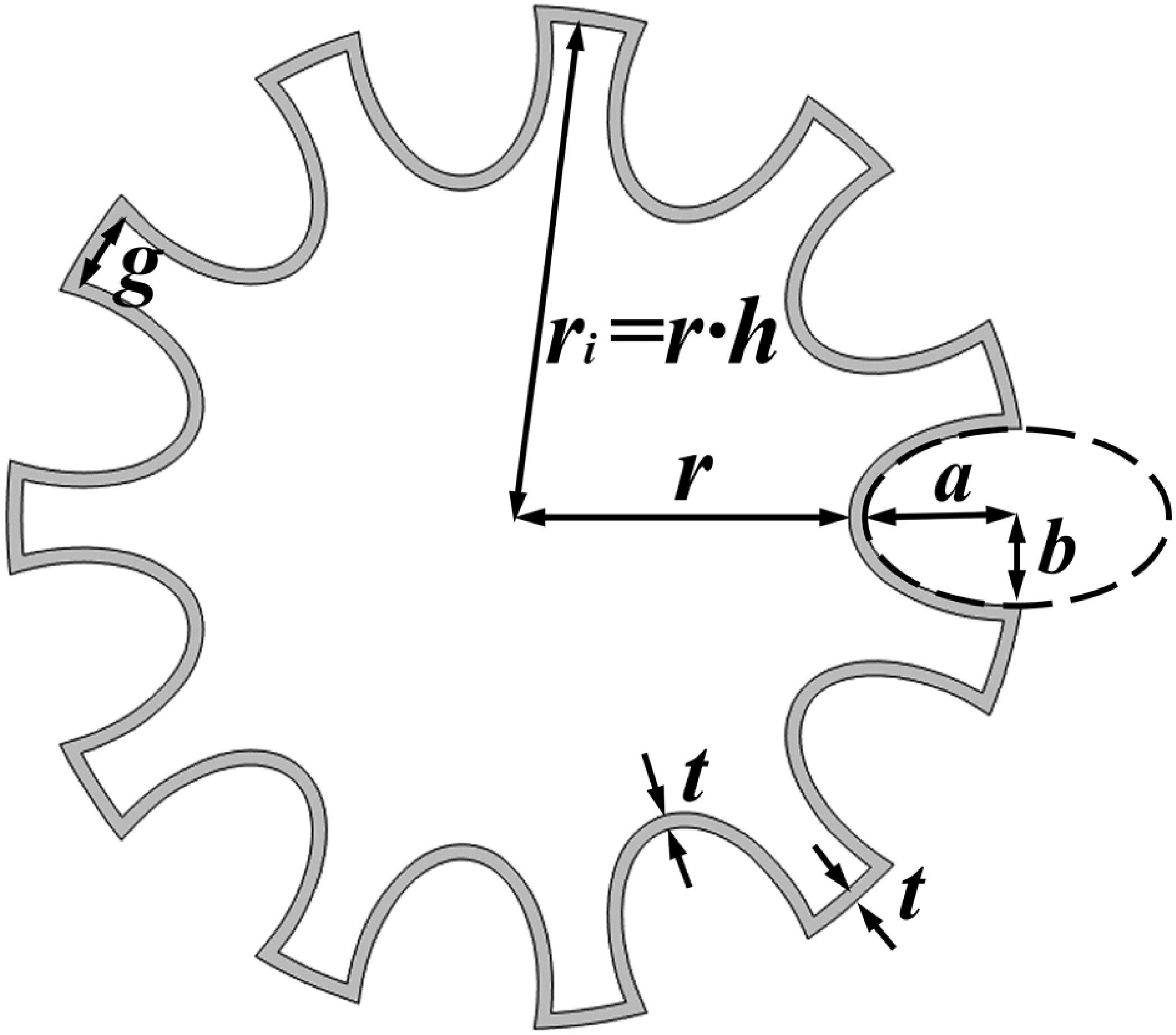
    Fig. 2. Fiber scheme and related parameters of the proposed THz NC-TF, where the air regions are white and the fiber material (TOPAS) regions are shaded.
    TL as a function of the curvature C and the number of negative curvature arcs M, with (a) h = 1.5 and (b) h = 1.725; four regions with different TL values are indicated.
    Fig. 3. TL as a function of the curvature C and the number of negative curvature arcs M, with (a) h = 1.5 and (b) h = 1.725; four regions with different TL values are indicated.
    Electric-field contour lines for four different regions in Fig. 3. (a) Heavy leakage through negative curvature arcs; (b) strong repulsion of the electric field; (c) heavy leakage through the gap; (d) strong coupling with tube walls.
    Fig. 4. Electric-field contour lines for four different regions in Fig. 3. (a) Heavy leakage through negative curvature arcs; (b) strong repulsion of the electric field; (c) heavy leakage through the gap; (d) strong coupling with tube walls.
    (a) TL spectra (0.7–1.6 THz) for TF (r = 4.5 mm), NC-TF (r = 4.5 mm, h = 1.5, C = 1.7, M = 6), and HRF (r = 4.5 mm, h = 1.5, C = 1.7, M = 6); (b) variation in TL with core radius r for TF, NC-TF, and HRF; (c) variation in TL with wall thickness t for TF, NC-TF, and HRF; (d) influence of bending radius (Rc) on TL.
    Fig. 5. (a) TL spectra (0.7–1.6 THz) for TF (r = 4.5 mm), NC-TF (r = 4.5 mm, h = 1.5, C = 1.7, M = 6), and HRF (r = 4.5 mm, h = 1.5, C = 1.7, M = 6); (b) variation in TL with core radius r for TF, NC-TF, and HRF; (c) variation in TL with wall thickness t for TF, NC-TF, and HRF; (d) influence of bending radius (Rc) on TL.
    (a) Schematic diagram of the fiber extrusion setup based on a commercial extruder and (b) photograph of the NC-TF extruded from the heated mold.
    Fig. 6. (a) Schematic diagram of the fiber extrusion setup based on a commercial extruder and (b) photograph of the NC-TF extruded from the heated mold.
    (a) Photograph of the specially designed extrusion mold and (b) scheme of the mold.
    Fig. 7. (a) Photograph of the specially designed extrusion mold and (b) scheme of the mold.
    Photographs of the extruded TOPAS COC THz fibers. (a) The NC-TF sample, (b) the TF sample, (c) the cross section of NC-TF, and (d) the cross section of TF.
    Fig. 8. Photographs of the extruded TOPAS COC THz fibers. (a) The NC-TF sample, (b) the TF sample, (c) the cross section of NC-TF, and (d) the cross section of TF.
    (a) The effective refractive index neff of the NC-TF and TF samples; (b) measured TL spectra for NC-TF and TF.
    Fig. 9. (a) The effective refractive index neff of the NC-TF and TF samples; (b) measured TL spectra for NC-TF and TF.
    (a) Mismatch of the outer body and the mold core (cross section); (b) simulated loss spectra of the nonideal NC-TF.
    Fig. 10. (a) Mismatch of the outer body and the mold core (cross section); (b) simulated loss spectra of the nonideal NC-TF.
    Xuan Yu, Fei Yu, Sheng Liu, Cheng Lei, Du Wang, "Single dielectric layer terahertz tube fiber with negative curvature," Chin. Opt. Lett. 23, 033701 (2025)
    Download Citation