
Chuang Sun, Hailong Pi, Kian Shen Kiang, Jun-Yu Ou, Jize Yan, "Arbitrary hybrid and higher-order Poincaré sphere beam generation by metasurfaces via a unified design framework," Adv. Photon. Nexus 4, 016015 (2025)
- Advanced Photonics Nexus
- Vol. 4, Issue 1, 016015 (2025)
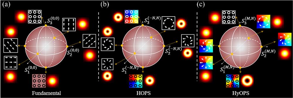
Fig. 1. (a) FPS, (b) HOPS, and (c) HyOPS.
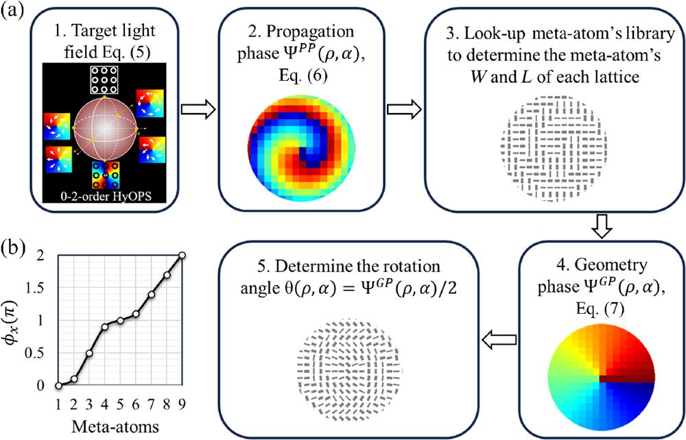
Fig. 2. (a) Design flow and (b) meta-atom’s library of the dielectric metasurface for generating HOPS and HyOPS beams.
Fig. 3. (a) Scheme of generating arbitrary VVBs on a target HOPS or HyOPS. (b) The circular point represents a scalar beam having a position angle
Fig. 4. (a) Simulated far-field, near-field, and phase profile distributions of the
Fig. 5. Experimental results: controlled generation of tightly focused fifth-order HOPS beams (a1)–(c3) along its longitude line and (d1)–(f3) along its equator. The first and fourth columns are the
Fig. 6. Simulation results: controlled generation of 0-2 order HyOPS beams (a1)–(c3) along its longitudinal line and (d1)–(f3) along its equator. The first and fourth columns are the
Fig. 7. Experimental results: controlled generation of 0-2 order HyOPS beams (a1)–(c3) along its longitudinal line and (d1)–(f3) along its equator. The first and fourth columns are the
Fig. 8. Simulation results: controlled generation of 0-1 order HyOPS beams (a1)–(c3) along its longitudinal line and (d1)–(f3) along its equator. The first and fourth columns are the
Fig. 9. Experimental results: controlled generation of 0-1 order HyOPS beams (a1)–(c3) along its longitudinal line and (d1)–(f3) along its equator. The first and fourth columns are the
|
Table 1. Parameters and target of metasurface samples.


Set citation alerts for the article
Please enter your email address

© Copyright 2018-2021 | Chinese Laser Press. All Rights Reserved 沪ICP备15018463号-20