The combination of an optical cavity and a proportional-integral (PI) controller is commonly used in experimental quantum optical fields. In this study, an optimal PI controller for an optical cavity was designed based on the average-squared value of the error signal. The controller was implemented using a field-programmable gate array (FPGA) data acquisition board and LabVIEW software. The overall gain of the controller is optimized by adopting the cavity transmission as an optical power reference, such that the cavity locking performance does not degrade as the optical power varies.
1 Introduction
The Fabry-Perot cavity,which is composed of two or more mirrors with high reflectivity,plays an important,multifunctional role in quantum optical experiments,such as in selecting and stabilizing the laser frequency [1-2],cleaning the laser transverse mode [3],reducing laser noise[4],and precision interferometry. A famous example is the interference gravitational wave detector,in which four coupled cavities are integrated into a Michelson interferometer to enhance the detection sensitivity [5-7].
However,the Fabry-Perot cavity is susceptible to the surrounding temperature and mechanical noise. Therefore,in most applications,it is locked on the resonance of the incident laser,or the laser frequency is locked to a specially fabricated,very stable cavity. Cavity detuning was measured and fed back using a proper controller. Schemes discriminating the error of cavity length include Pound-Drever-Hall locking[8],transmission locking [9],Hänsch-Couillaud lock[10],tilt lock[11],and homodyne locking[12]. An effective controller is essential to form a stable anti-noise optical system. The amplitude amplification and phase delay of the measured error signal must be tailored to fit the optical system.
In recent decades,digital locking of optical cavities has been widely adopted. Digital locking has several advantages over other analog devices. It provides good scalability and integration,which are particularly important in complicated experimental systems[13-14]. It also offers flexibility and programming capabilities. Often,flexible programming of cavity-locking controllers is required:for example,in controlling multi-input multi-output systems[15],identifying atomic absorption lines,and locking laser frequency[16].
Proportional-integral(PI)controllers are widely used in many applications owing to their simplicity and effectiveness. Extensive research has been conducted on PI parameter tuning,such as the Ziegler-Nichols parameter tuning [17]. Most methods require system knowledge,which can be acquired through experimental measurements. However,in practice,most users empirically tune the PI parameters through trial and error. This method is highly dependent on the experience of the experimenter. In contrast,modern control techniques[18],such as linear quadratic regulators,are recently used in optical cavity locking. These methods define a cost function to optimize the control parameters. However,a sophisticated control theory is required to design such controllers.
In this study,an optimal PI controller for the cavity was designed and implemented using a reconfigurable I/O device and LabVIEW programming(LabVIEW FPGA,NI-7833R). The controller parameters are optimized by minimizing the average squared error signal of the system. The total gain of the controller is optimized by adopting the cavity transmission as the optical power reference,such that the cavity-locking performance will not degrade as the optical power varies.
2 Experimental setup
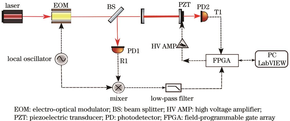
The traditional Pound-Drever-Hall(PDH)technique [8] was adopted to discriminate the error of the cavity length. Field-programmable gate arrays(FPGA)and LabVIEW were used to design the controller. The experimental setup is illustrated in Fig. 1,the laser beams are represented by solid lines,whereas electronic signals are represented by dotted lines. A phase-modulated laser beam(90 MHz)was injected into a linear cavity whose detuning was driven by a piezo transducer(PZT). The cavity was composed of two mirrors with a spacing of 28 mm.
The mirrors have a power transmittance of T=10%,T=0.1%,and radii of curvature of 30 mm and infinity,respectively.
The reflected light was picked off using a 50% beam splitter and detected using a wideband photodetector(PD1). The subsequent photocurrent was demodulated with reference to the same local oscillator used to modulate the laser. After passing through a low-pass filter,the demodulated signal was used as the error signal for cavity detuning. The laser transmitted through the optical cavity was detected by another photodetector(PD2),and the subsequent photocurrent was used as a reference for optical power. The error signal and optical power reference are sent to an analog-to-digital converter and converted into digital signals. The digital program of the controller running on the FPGA was composed and debugged using the LabVIEW software.
The programming output was converted to an analog signal by a digital-to-analog converter connected to a high-voltage amplifier and then to the cavity PZT to drive cavity detuning.
A schematic of the control system is shown in Fig. 2. is the transfer function of the controller, is the transfer function of the plant, represents the set point,and represents the cavity detuning error signal. The blue part is the schematic diagram of the frequency response measurement. The error signal of the optical cavity(plant)is processed using a digital PI controller,whose parameter optimization is introduced in the following section and then fed back to the cavity. The closed-loop frequency response was measured when the cavity was locked in resonance by injecting a chirped sinusoidal signal into the piezo and detecting the corresponding error signal.
Figure 2.Schematic diagram of closed-loop feedback control
The mathematical expression of discrete PI can be written as
,
where is the error signal value sampled at time, is the overall gain, is the integration time,and is the sampling period,which was μ in the experiment. is the control signal fed back to the piezo through a high-voltage amplifier.
The PI controller program has two external inputs:the error signal and the reference of the optical power in the cavity. The gain of the plant is proportional to the optical power in the cavity[19]. To keep the open-loop overall gain unchanged as the optical power varies,the overall gain of the PI is set to ,where is the real-time value of the optical power reference. is the optimal overall gain of the PI controller when the reference of optical power detected by PD2 is . This optimal overall gain,together with the integration gain,,was determined by minimizing the average squared error signal when scanning the two-dimensional parameter space. When the overall gain is less than the optimal value,the environmental noise will not be sufficiently suppressed,the cavity will be detuned,and the average squared error signal will increase. When the overall gainis larger than the optimal value ,the cavity detuning will not be disturbed by environmental noise,but the control signal will be too strong at this time,the system will also oscillate,and the average squared will increase. Thus,for a certain optical power,an optimal parameter combination exists that minimizes the average squared error signal.
The experimental results of parameter scanning are shown in Fig. 3. The grid contained data points. The horizontal axis corresponds to the proportional gain ,whereas the vertical axis represents the integration gain . The average-squared value of each point in the grid is calculated using 100 data points of the error signal ,. As shown in Fig. 3,the average squared value of the central area is low,and that of the surrounding area is high. Under the peripheral parameters,the cavity-locking performance worsens. The error signal oscillates or drifts,as previously explained. and are selected as the optimal PI control parameters.
Figure 3.Hot spot of the average squared error signal
This experiment was performed using a Moku:Lab instrument to measure the frequency response. As shown in Fig. 2,the frequency response of the system was measured using a signal analyzer by injecting a chirped sinusoidal signal into the piezo and detecting the corresponding error signal.
Fig. 4 shows the open-loop frequency response of the system without a servo controller and the closed-loop frequency response of the system with a servo controller,revealing that the digital control system largely suppressed the vibrating noise below . The system bandwidth is primarily limited by the mechanical resonance of the piezoelectric actuator. Fig. 5 shows the noise spectrum of the error signal in the locked and unlocked states. The peak at indicates a slight oscillation at the edge of the control bandwidth. The noise floor was measured when the Fabry-Perot cavity did not resonate.
To verify the control capability of the designed digital control system under the condition of laser power variation,the incident laser was intensity modulated by a square wave. Fig. 6(a)shows the error signal and cavity transmission with a adapted overall gain. Fig. 6(b)shows the error signal and cavity transmission with the non-adapted overall gain. The red line represents the error signal,and the blue line represents the cavity transmission. It can be observed that the adapted overall gain can effectively maintain the system stability when the laser power is varied.
Figure 6.Cavity transmission power and error signal. (a) Adapted overall gain; (b) non-adapted overall gain
A digital proportional-integral controller was designed and implemented for the optical cavity. The overall gain of the controller was optimized in the case of laser power variations. The proportional and integral gains of the controller were optimized by minimizing the average square of the error signal. The measured frequency response showed that the cavity length was robustly controlled against disturbances,and the spectrum of the error signal indicated that the controller provided good noise suppression. The entire system exhibits good long-term stability. This digital control system can provide the basis for a more complicated optical system.