
Xian Liu, Zehui Zhai, Jianli Liu, Xufei Han. [J]. Laser & Optoelectronics Progress, 2023, 60(15): 1536001
- Laser & Optoelectronics Progress
- Vol. 60, Issue 15, 1536001 (2023)
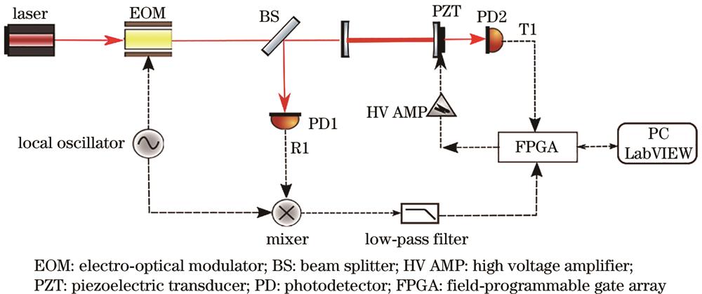
Fig. 1. Experimental setup diagram
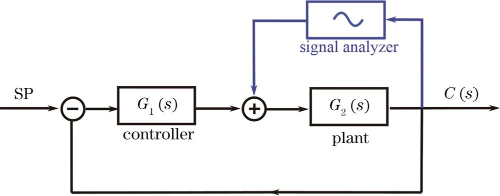
Fig. 2. Schematic diagram of closed-loop feedback control
Fig. 3. Hot spot of the average squared error signal
Fig. 4. Frequency response diagram of the system
Fig. 5. Error signal spectrum
Fig. 6. Cavity transmission power and error signal. (a) Adapted overall gain; (b) non-adapted overall gain


Set citation alerts for the article
Please enter your email address

© Copyright 2018-2021 | Chinese Laser Press. All Rights Reserved 沪ICP备15018463号-20