• Infrared and Laser Engineering
  • Vol. 52, Issue 3, 20220554 (2023)
Hongwei Gao1, Zhongming Yang2, Hongbo Liu3, Xingang Zhuang3, and Zhaojun Liu2
Author Affiliations
  • 1Key Laboratory of Laser & Infrared System, Ministry of Education, Shandong University, Qingdao 266237, China
  • 2School of Information Science and Engineering, Shandong University, Qingdao 266237, China
  • 3East China Institute of Electronic Measurement Instrument, Qingdao 266555, China
  • show less
    DOI: 10.3788/IRLA20220554 Cite this Article
    Hongwei Gao, Zhongming Yang, Hongbo Liu, Xingang Zhuang, Zhaojun Liu. Design of portable infrared target simulator system[J]. Infrared and Laser Engineering, 2023, 52(3): 20220554 Copy Citation Text show less
    Block diagram of portable infrared target simulation system
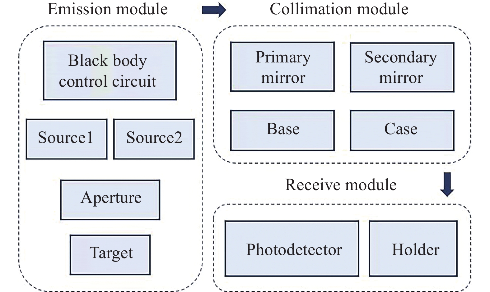
    Fig. 1. Block diagram of portable infrared target simulation system
    Layout of optical system
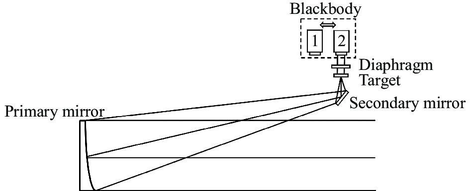
    Fig. 2. Layout of optical system
    (a) 2D and (b) 3D layout of collimator system
    Fig. 3. (a) 2D and (b) 3D layout of collimator system
    Wavefront diagram at the exit of the system pupil
    Fig. 4. Wavefront diagram at the exit of the system pupil
    Design of mechanical structure
    Fig. 5. Design of mechanical structure
    Optical machine thermal integrated analysis process
    Fig. 6. Optical machine thermal integrated analysis process
    Model of finite element analysis
    Fig. 7. Model of finite element analysis
    Result of finite element analysis of the primary mirror (a) and the secondary mirror (b)
    Fig. 8. Result of finite element analysis of the primary mirror (a) and the secondary mirror (b)
    Wavefront plot with a temperature difference of 30 ℃
    Fig. 9. Wavefront plot with a temperature difference of 30 ℃
    (a) Structure of target holder; (b) Target patterns
    Fig. 10. (a) Structure of target holder; (b) Target patterns
    Fabricating of infrared target simulation system
    Fig. 11. Fabricating of infrared target simulation system
    System installation and commissioning steps
    Fig. 12. System installation and commissioning steps
    Adjustment result of collimator system
    Fig. 13. Adjustment result of collimator system
    Imaging results at 10 m distance
    Fig. 14. Imaging results at 10 m distance
    VariableValue
    Primary mirror diameter/mm106
    Focal length/mm716
    Field of view/(°)1
    Off-axis volume/mm160
    Secondary mirror diameter/mm56
    Table 1. Paraxial parameters of collimator
    Wavelength/μmField of viewPV/λRMS/λ
    40.01320.0038
    40.04880.0097
    120.025°/1′30″0.00440.0013
    120.025°/1′30″0.01630.0032
    Table 2. Results of wavefront analysis
    RMS/λPV/λ
    Primary mirror0.00140.0076
    Second mirror0.00060.0037
    Table 3. Shape variable of primary and second mirrors with a temperature difference of 30 ℃
    X/mm Y/mm Z/mm Rz/(″) Ry/(″)
    Primary mirror0.0712−0.2157−0.0185−0.03761.1893
    Second mirror0.0714−0.00430.02750.2911−1.5359
    Table 4. Rigid body change value of primary and second mirrors with a temperature difference of 30 ℃
    CoefficientValue/λnmRepresentation
    ZFR 00.000001
    ZFR 1−0.00111ρcos(θ)
    ZFR 2−0.0011−1ρsin(θ)
    ZFR 30.00120−1+2ρ2
    ZFR 4−0.05722ρ2cos(2θ)
    ZFR 50.0642−2ρ2sin(2θ)
    ZFR 6−0.01631(−2ρ+3ρ3)cos(θ)
    ZFR 7−0.0933−1(−2ρ+3ρ3)sin(θ)
    ZFR 80.025401–6ρ2+6ρ4
    ZFR 90.09733ρ3cos(3θ)
    ZFR 10−0.0553−3ρ3sin(3θ)
    ZFR 11−0.00942(−3ρ2+4ρ4)cos(2θ)
    ZFR 120.0354−2(−3ρ2+4ρ4)sin(2θ)
    Table 5. Zernike coefficients of collimator
    Hongwei Gao, Zhongming Yang, Hongbo Liu, Xingang Zhuang, Zhaojun Liu. Design of portable infrared target simulator system[J]. Infrared and Laser Engineering, 2023, 52(3): 20220554
    Download Citation