
Luotian Huang, Gengqin Liang, Zongge Li, Peiguang Yan, Jinchuan Guo. Research Progress on Tunable Narrow Linewidth Semiconductor Lasers Integrated with External Cavity[J]. Laser & Optoelectronics Progress, 2025, 62(3): 0300001
- Laser & Optoelectronics Progress
- Vol. 62, Issue 3, 0300001 (2025)
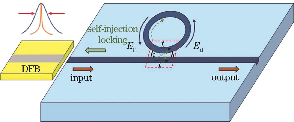
Fig. 1. Structure diagram of passive external cavity semiconductor laser
![Composite cavity can be equivalent to a mirror with equivalent reflectivity[19]](/richHtml/lop/2025/62/3/0300001/img_02.jpg)
Fig. 2. Composite cavity can be equivalent to a mirror with equivalent reflectivity[19]
Fig. 3. Structure diagram of a basically wide-tunable III-V/Si based on multi-ring mirrors[37]
Fig. 4. Tunable laser with SOA and external resonator. (a) Structure diagram[38]; (b) spectra of tunable lasers with different wavelengths[38]; (c) schematic of laser structure with asymmetric MZI[41]; (d) wavelength tuning of laser with asymmetry MZI at 90 mA injection current[41]; (e) calculated and measured linewidth versus output power plot[41]; (f) schematic of tunable laser integrated with SOA and silicon photonic filter chip[43]; (g) laser spectrum in the 65 nm range[43]
Fig. 5. Concept diagram of a wide tunable laser array covering the entire low-loss fiber optic telecommunications window[46]. (a) Schematic of Si ring resonator lasers bonded with III-V gain materials in O-band, E-band, and S-C-L bands on common SOI wafers; (b) microscope images of ring resonators, phase shifters, and ring mirrors
Fig. 6. Structure diagram of tunable laser based on an air bridge structure waveguide ring cavity[53]
Fig. 7. External cavity narrow linewidth laser[12]. (a) Structure diagram; (b) spectrum of lasers (tuning range is from 1545.5 nm to 1550.4 nm); (c) frequency noise of a free-running DFB laser and the proposed external cavity laser corresponding to an intrinsic linewidth of 49.70 kHz and 27.17 Hz, respectively
Fig. 8. InP-Si3N4 hybrid laser.(a) Schematic diagram of a hybrid laser[57]; (b) superimposed spectra when coarsely tuning over a 43 nm wide range (left), superimposed spectra when fine-tuning over a range of 0.8 nm via tuning both MRRs simultaneously (right), achieving a stepwise sweeping of the wavelength at the FSR of the whole laser cavity[59]; (c) recorded beat signal at a driving current of 196 mA and a laser output wavelength of 1578.12 nm, Lorentz fitting linewidth is 87 kHz[60]; (d) schematic diagram of a laser integrating InP and GaAs gain chips[61]; (e) superimposed spectra when thermally tuning a microresonator, and the tuning range is 46 nm[61]; (f) recorded RF beat spectrum (red dots), the blue line shows a Lorentzian fit corresponding to a laser linewidth of 18 kHz[61]; (g) schematic diagram of the III-V/Si3N4 hybrid laser[63]; (h) superimposed spectra, tuning range is 172 nm[64]
Fig. 9. Vision of the integrated platform[65](inset: microscope image of the ring resonator before microheater deposition, and the waveguide is fabricated using 175 nm thick Si3N4 surrounded by SiO2)
Fig. 10. Narrow linewidth self-injection locked laser. (a) Schematic of laser structure[75]; (b) comparison of linewidth between free-running DFB laser and laser locked into LN micro ring cavity by self-injection[75]; (c) tuning of laser wavelength by applying electrical power[75]; (d) schematic of narrow linewidth laser hybrid integration with external cavity chip and commercial DFB laser[78]; (e) frequency noise of the laser using LN external cavity chip is reduced by 1/169 compared to free-running DFB, and linewidth is reduced to 2.5 kHz[78]; (f) emission spectra[78]
|
|
Table 2. Performance comparison of integrated passive external cavity semiconductor lasers with different materials


Set citation alerts for the article
Please enter your email address

© Copyright 2018-2021 | Chinese Laser Press. All Rights Reserved 沪ICP备15018463号-20