• Chinese Optics Letters
  • Vol. 23, Issue 2, 020601 (2025)
Shaoshao Yu1,2, Wenyu Zhao1,2, Xin Wang1,2, Xinghua Li1,2, and Shougang Zhang1,2,*
Author Affiliations
  • 1Key Laboratory of Time Reference and Applications, National Time Service Center, Chinese Academy of Sciences, Xi’an 710600, China
  • 2University of Chinese Academy of Sciences, Beijing 100049, China
  • show less
    DOI: 10.3788/COL202523.020601 Cite this Article Set citation alerts
    Shaoshao Yu, Wenyu Zhao, Xin Wang, Xinghua Li, Shougang Zhang, "Novel compensation technique for mitigating dispersion in fiber-optic microwave frequency transfer systems," Chin. Opt. Lett. 23, 020601 (2025) Copy Citation Text show less
    Architecture of the compensation system for fiber-based microwave transfer. VCO, voltage-controlled oscillator; PLL, phase-locked loop; FOC, fiber optic circulator; DCF, dispersion-compensating fiber; PD, photodiode.
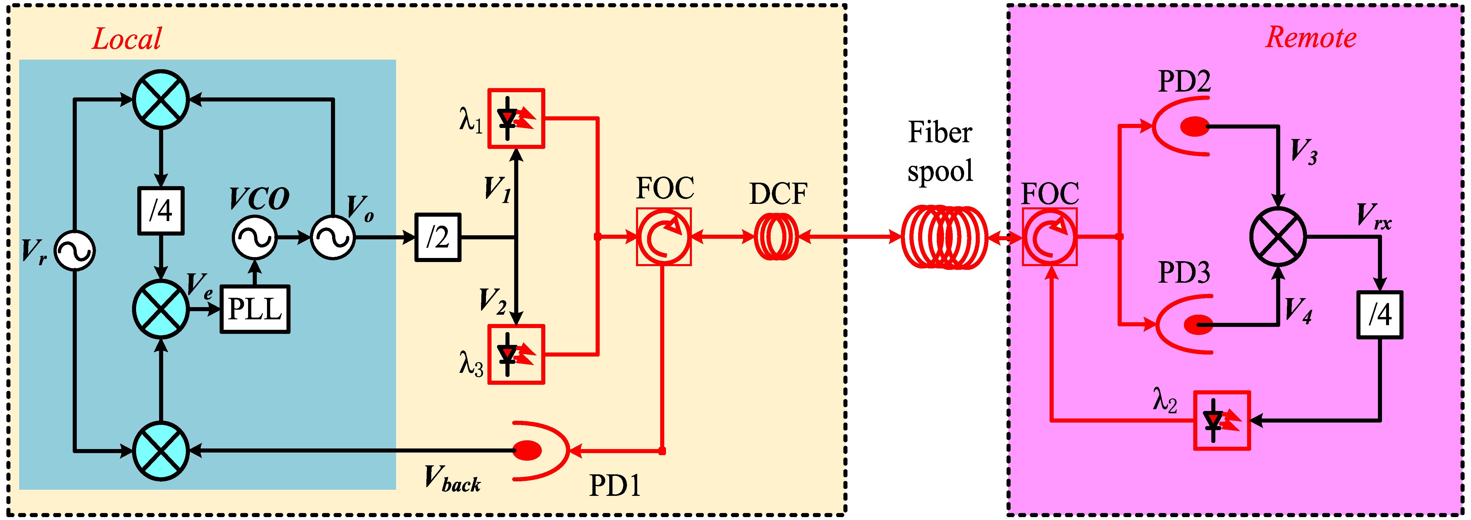
    Fig. 1. Architecture of the compensation system for fiber-based microwave transfer. VCO, voltage-controlled oscillator; PLL, phase-locked loop; FOC, fiber optic circulator; DCF, dispersion-compensating fiber; PD, photodiode.
    Schematic diagram of the microwave frequency transfer system. OCXO, over-controlled crystal oscillator; PDRO, phase-locked dielectric resonant oscillator; MZM, Mach–Zehnder modulator; PS, polarization scrambler; WDM, wavelength division multiplexing; DCF, dispersion-compensating fiber; Bi-EDFA, bidirectional erbium-doped fiber amplifier.
    Fig. 2. Schematic diagram of the microwave frequency transfer system. OCXO, over-controlled crystal oscillator; PDRO, phase-locked dielectric resonant oscillator; MZM, Mach–Zehnder modulator; PS, polarization scrambler; WDM, wavelength division multiplexing; DCF, dispersion-compensating fiber; Bi-EDFA, bidirectional erbium-doped fiber amplifier.
    Temporal behaviors of the propagation delay of the previous scheme (black trace) and the propagation delay of the new scheme (red trace).
    Fig. 3. Temporal behaviors of the propagation delay of the previous scheme (black trace) and the propagation delay of the new scheme (red trace).
    Fractional frequency instability of the 100 km link: the previous scheme (black squares), the new scheme (red circles), and the system noise floor with an optical attenuation to shorten the link (blue triangles).
    Fig. 4. Fractional frequency instability of the 100 km link: the previous scheme (black squares), the new scheme (red circles), and the system noise floor with an optical attenuation to shorten the link (blue triangles).
    Propagation delay variation as a function of the ambient temperature of the fiber link. (a) The previous scheme used laser wavelengths of 1550.92 and 1551.72 nm. (b) The previous scheme used laser wavelengths of 1551.72 and 1552.52 nm. (c) The new scheme used laser wavelengths of 1550.92, 1551.72, and 1552.52 nm.
    Fig. 5. Propagation delay variation as a function of the ambient temperature of the fiber link. (a) The previous scheme used laser wavelengths of 1550.92 and 1551.72 nm. (b) The previous scheme used laser wavelengths of 1551.72 and 1552.52 nm. (c) The new scheme used laser wavelengths of 1550.92, 1551.72, and 1552.52 nm.
    Shaoshao Yu, Wenyu Zhao, Xin Wang, Xinghua Li, Shougang Zhang, "Novel compensation technique for mitigating dispersion in fiber-optic microwave frequency transfer systems," Chin. Opt. Lett. 23, 020601 (2025)
    Download Citation